Nissan Versa (N17): C1116 Stop lamp switch
DTC Logic
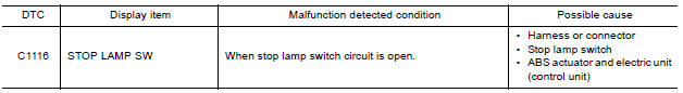
DTC DETECTION LOGIC
DTC CONFIRMATION PROCEDURE
1.CHECK SELF-DIAGNOSIS RESULTS
Check the self-diagnosis results.
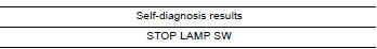
Is above displayed on the self-diagnosis display?
YES >> Proceed to diagnosis procedure. Refer to BRC "Diagnosis Procedure".
NO >> Inspection End.
Diagnosis Procedure
Regarding Wiring Diagram information, refer to BRC "Wiring Diagram".
1.CONNECTOR INSPECTION
- Disconnect stop lamp switch connector and ABS actuator and electric unit (control unit) connector.
- Check terminals for deformation, disconnection, looseness or damage.
Is the inspection result normal?
YES >> GO TO 2
NO >> Repair or replace as necessary.
2.CHECK STOP LAMP SWITCH CIRCUIT
- Connect stop lamp switch connector.
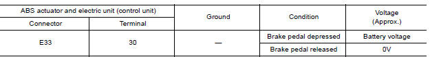
- Check voltage between ABS actuator and electric unit (control unit)
connector E33 terminal 30 and
ground.
Is the inspection result normal?
YES >> Replace ABS actuator and electric unit (control unit). Refer to BRC "Removal and Installation".
NO >> GO TO 3
3.CHECK STOP LAMP SWITCH CIRCUIT FOR OPEN
- Disconnect stop lamp switch connector.
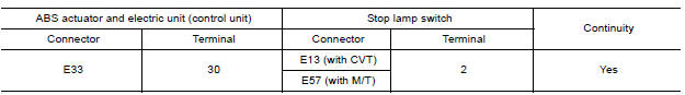
- Check continuity between ABS actuator and electric unit (control unit)
connector E33 terminal 30 and stop
lamp switch connector E13 (with CVT) or E57 (with M/T) terminal 2.
Is the inspection result normal?
YES >> GO TO 4.
NO >> Repair or replace as necessary.
4.CHECK STOP LAMP SWITCH CIRCUIT FOR SHORT
Check continuity between ABS actuator and electric unit (control unit)
connector E33 terminal 30 and ground.
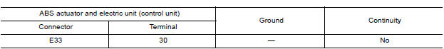
Is the inspection result normal?
YES >> Replace stop lamp switch.
NO >> Repair harness or connectors.
 C1115 ABS Sensor [abnormal signal]
Other materials:
Consult function
APPLICATION ITEMS
Diagnostic test mode
Function
Work Support
This mode enables a technician to adjust some devices faster and
more accurately.
Self Diagnostic Results
Retrieve DTC from ECU and display diagnostic items.
Data Monitor
Monitor the input ...
Air breather hose
Removal and Installation
REMOVAL
Remove air duct (inlet). Refer to EM "Exploded View".
Remove air breather hose from transaxle assembly.
INSTALLATION
Installation is in the reverse order of removal.
CAUTION:
Check that air breather hose is not collapsed or blocked due to ...
Categories
- Manuals Home
- Nissan Versa Owners Manual
- Nissan Versa Service Manual
- Video Guides
- Questions & Answers
- External Resources
- Latest Updates
- Most Popular
- Sitemap
- Search the site
- Privacy Policy
- Contact Us

0.0058