Nissan Versa (N17): P0078 EVT control solenoid valve
DTC Logic
DTC DETECTION LOGIC
| DTC No. | Trouble diagnosis name (Trouble diagnosis content) | DTC detecting condition | Possible cause |
| P0078 | EX V/T ACT/CIRCB1 (Exhaust valve timing control solenoid valve circuit) | An improper voltage is sent to the ECM through exhaust valve timing control solenoid valve. |
|
DTC CONFIRMATION PROCEDURE
1.PRECONDITIONING
If DTC Confirmation Procedure has been previously conducted, always perform the following procedure before conducting the next test.
- Turn ignition switch OFF and wait at least 10 seconds.
- Turn ignition switch ON.
- Turn ignition switch OFF and wait at least 10 seconds.
>> GO TO2.
2.PERFORM DTC CONFIRMATION PROCEDURE
- Start engine and let it idle for 5 seconds.
- Check 1st trip DTC.
Is 1st trip DTC detected?
YES >> Proceed to EC, "Diagnosis Procedure".
NO >> INSPECTION END
Diagnosis Procedure
1.CHECK EXHAUST VALVE TIMING CONTROL SOLENOID VALVE POWER SUPPLY
- Turn ignition switch OFF.
- Disconnect exhaust valve timing (EVT) control solenoid valve harness connector.
- Turn ignition switch ON.
- Check the voltage between exhaust valve timing control solenoid valve harness connector and ground.
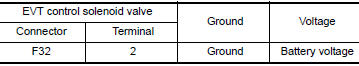
Is the inspection result normal?
YES >> GO TO 3.
NO >> GO TO 2.
2.CHECK EXHAUST VALVE TIMING CONTROL SOLENOID VALVE POWER SUPPLY CIRCUIT
- Turn ignition switch OFF.
- Disconnect IPDM E/R harness connector.
- Check the continuity between EVT control solenoid valve harness connector and IPDM E/R harness connector.
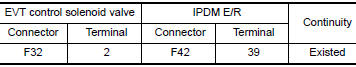
4. Also check harness for short to ground.
Is the inspection result normal?
YES >> Perform the trouble diagnosis for power supply circuit.
NO >> Repair or replace errordetected parts.
3.CHECK EXHAUST VALVE TIMING CONTROL SOLENOID VALVE GROUND CIRCUIT
- Turn ignition switch OFF.
- Disconnect ECM harness connector.
- Check the continuity between EVT control solenoid valve harness connector and ECM harness connector.
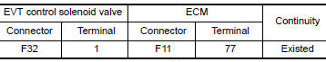
4. Also check harness for short to ground and to power.
Is the inspection result normal?
YES >> GO TO 4.
NO >> Repair or replace errordetected parts.
4.CHECK EXHAUST VALVE TIMING CONTROL SOLENOID VALVE
Check the exhaust valve timing control solenoid valve. Refer to EM, "Exploded View".
Is the inspection result normal?
YES >> Check intermittent incident. Refer to GI, "Intermittent Incident".
NO >> Replace exhaust valve timing control solenoid valve.
Component Inspection
1.CHECK EXHAUST VALVE TIMING CONTROL SOLENOID VALVEI
- Turn ignition switch OFF.
- Disconnect exhaust valve timing control solenoid valve harness connector.
- Check resistance between exhaust valve timing control solenoid valve terminals as per the following.
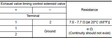
Is the inspection result normal?
YES >> GO TO 2.
NO >> Replace exhaust valve timing control solenoid valve. Refer to EM, "Exploded View".
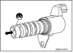
2.CHECK EXHAUST VALVE TIMING CONTROL SOLENOID VALVEII
- Remove exhaust valve timing control solenoid valve. Refer to EM, "Exploded View".
- Provide 12 V DC between exhaust valve timing control solenoid
valve terminals 1 and 2, and then interrupt it. Check that the
plunger moves as shown in the figure.
CAUTION: Do not apply 12 V DC continuously for 5 seconds or more.
Doing so may result in damage to the coil in exhaust valve timing control solenoid valve.
NOTE: Always replace Oring when exhaust valve timing control solenoid valve is removed.
Is the inspection result normal?
YES >> INSPECTION END
NO >> Replace exhaust valve timing control solenoid valve. Refer to EM56, "Exploded View".
 P0075 IVT control solenoid valve
Other materials:
P1212 TCS communication line
Description
This CAN communication line is used to control the smooth engine operation
during the TCS operation. Pulse
signals are exchanged between ECM and "ABS actuator and electric unit (control
unit)".
Be sure to erase the malfunction information such as DTC not only for "ABS
actuat ...
Shift change control
Shift change control : system diagram
Shift change control : system description
The clutch is controlled with the optimum timing and oil pressure by the
engine speed, engine torque information,
etc.
Shift Change System Diagram
*1: Full phase real-time feedback control monitors m ...
Categories
- Manuals Home
- Nissan Versa Owners Manual
- Nissan Versa Service Manual
- Video Guides
- Questions & Answers
- External Resources
- Latest Updates
- Most Popular
- Sitemap
- Search the site
- Privacy Policy
- Contact Us

0.0055