Nissan Versa (N17): ECM Branch line circuit
Diagnosis Procedure
1.CHECK CONNECTOR
1. Turn the ignition switch OFF.
2. Disconnect the battery cable from the negative terminal.
3. Check the terminals and connectors of the ECM for damage, bend and loose connection (unit side and connector side).
Is the inspection result normal?
YES >> GO TO 2.
NO >> Repair the terminal and connector.
2.CHECK HARNESS FOR OPEN CIRCUIT
1. Disconnect the connector of ECM.
2. Check the resistance between the ECM harness connector terminals.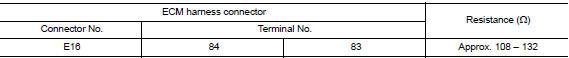
Is the measurement value within the specification?
YES >> GO TO 3.
NO >> Repair the ECM branch line.
3.CHECK POWER SUPPLY AND GROUND CIRCUIT
Check the power supply and the ground circuit of the ECM. Refer to EC "Diagnosis Procedure".
Is the inspection result normal?
YES (Present error)>>Replace the ECM. Refer to EC "Removal and Installation".
YES (Past error)>>Error was detected in the ECM branch line.
NO >> Repair the power supply and the ground circuit.
 Main line between IPDM-E and DLC
circuit
Main line between IPDM-E and DLC
circuit
Diagnosis Procedure 1.CHECK CONNECTOR 1. Turn the ignition switch OFF. 2. Disconnect the battery cable from the negative terminal. 3. Check the following terminals and connectors for damage, ben ...
ABS Branch line circuit
Diagnosis Procedure 1.CHECK CONNECTOR 1. Turn the ignition switch OFF. 2. Disconnect the battery cable from the negative terminal. 3. Check the terminals and connectors of the ABS actuator and e ...
Other materials:
Seat belt retractor
SEAT BELT RETRACTOR : Removal and Installation
REMOVAL
CAUTION:
Before servicing, turn ignition switch OFF, disconnect battery negative terminal
and wait at least three
minutes.
Disconnect both the negative and positive battery cables, then wait at
least three minutes. Refer to PG " ...
Rear regulator
Exploded View
1. Rear door panel 2. Sealing screen 3. Rear door sash
4. Rear power window motor 5. Regulator assembly 6. Partition sash
7. Partition glass 8. Rear door glass 9. Partition weather-strip
10. Rear door glass run 11. Regulator seal (manual window) 12. Retaining clip
(manual win ...
Categories
- Manuals Home
- Nissan Versa Owners Manual
- Nissan Versa Service Manual
- Video Guides
- Questions & Answers
- External Resources
- Latest Updates
- Most Popular
- Sitemap
- Search the site
- Privacy Policy
- Contact Us

0.0048