Nissan Versa (N17): ABS Actuator and electric unit (control unit)
Reference Value
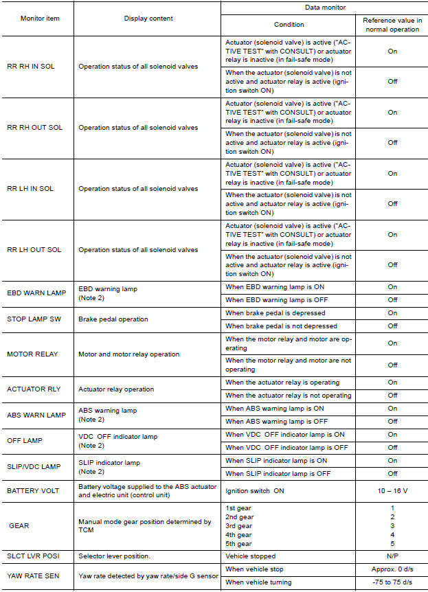
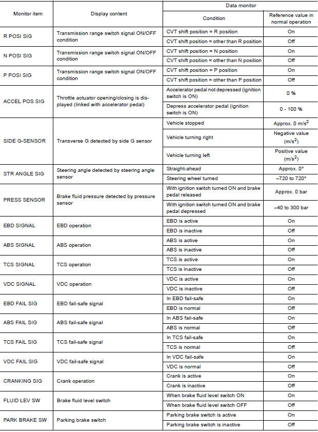
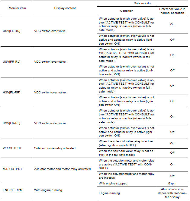
VALUES ON THE DIAGNOSIS TOOL
CAUTION: The display shows the control unit calculation data, so a normal value might be displayed even in the event the output circuit (harness) is open or short-circuited.
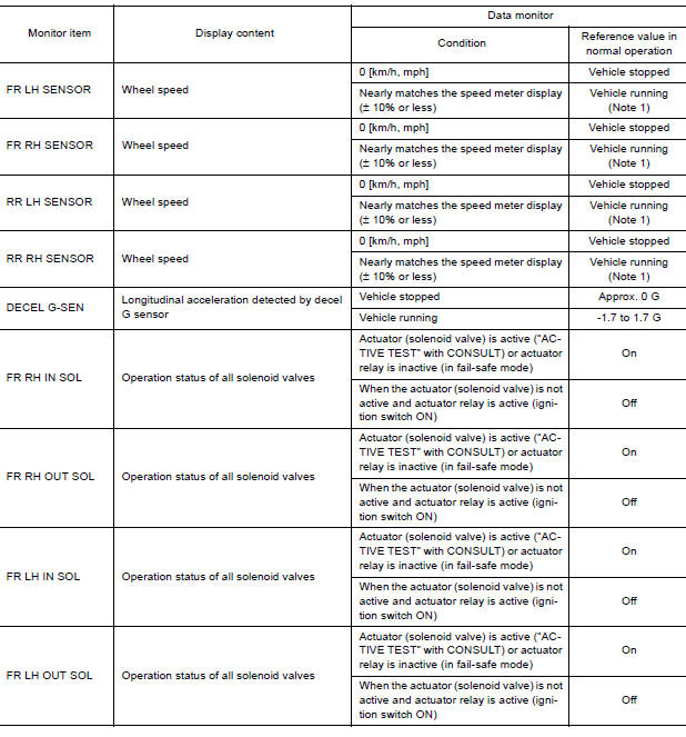
Note 1: Confirm tire pressure is normal.
Note 2: On and off timing for warning lamps and indicator lamps.
- Refer to BRC "VDC/TCS/ABS : VDC Function".
- Refer to BRC "VDC/TCS/ABS : TCS Function".
- Refer to BRC "VDC/TCS/ABS : ABS Function".
- Refer to BRC "VDC/TCS/ABS : EBD Function".
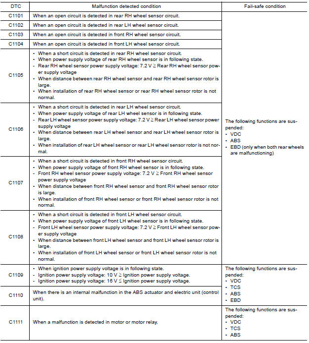
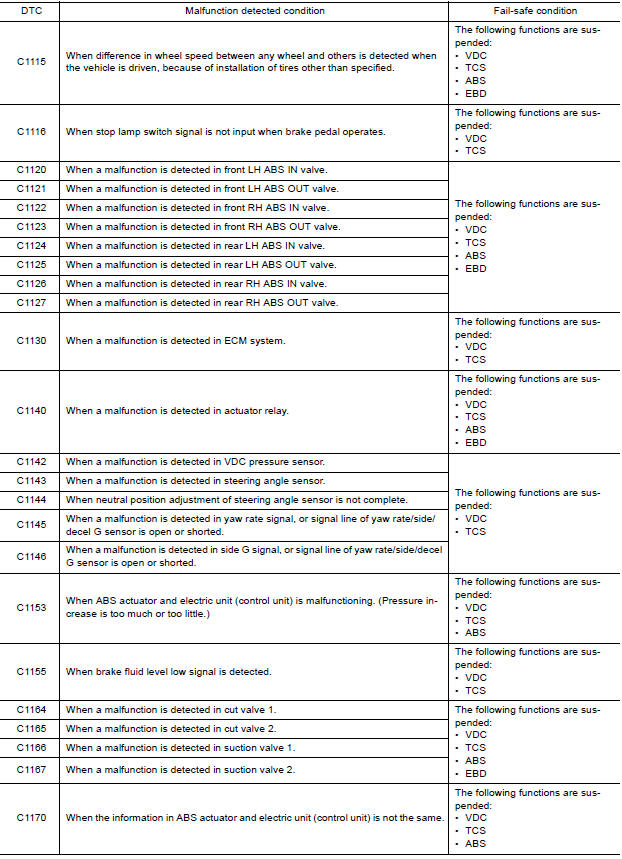
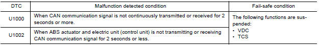
Fail-safe
VDC AND TCS FUNCTIONS
VDC warning lamp in combination meter turns ON when a malfunction occurs in system [ABS actuator and electric unit (control unit)]. The control is suspended for VDC and TCS functions. However, ABS and EBD functions operate normally.
ABS FUNCTION
ABS warning lamp and SLIP indicator lamp in combination meter turn ON when a malfunction occurs in system [ABS actuator and electric unit (control unit)]. The control is suspended for VDC, TCS and ABS functions.
However, EBD functions operate normally.
EBD FUNCTION
ABS warning lamp, brake warning lamp and SLIP indicator lamp in combination meter turn ON when a malfunction occurs in system [ABS actuator and electric unit (control unit)]. The control is suspended for VDC, TCS, ABS and EBD functions.
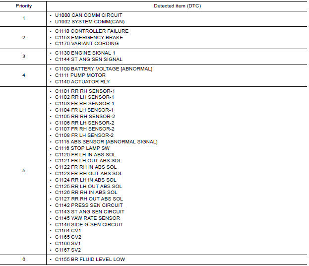
DTC Inspection Priority Chart
When multiple DTCs are displayed simultaneously, check each one using the following priority list.
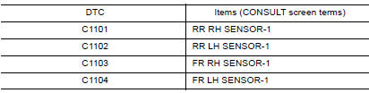
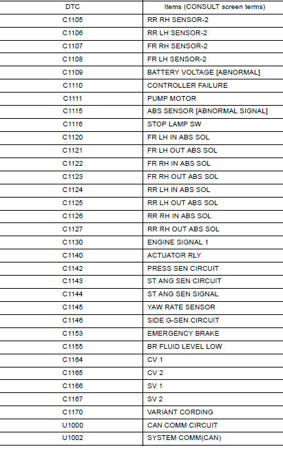
DTC Index
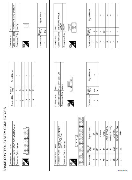
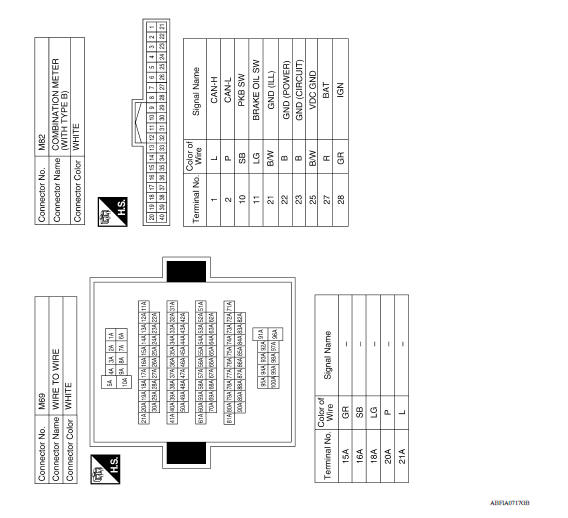
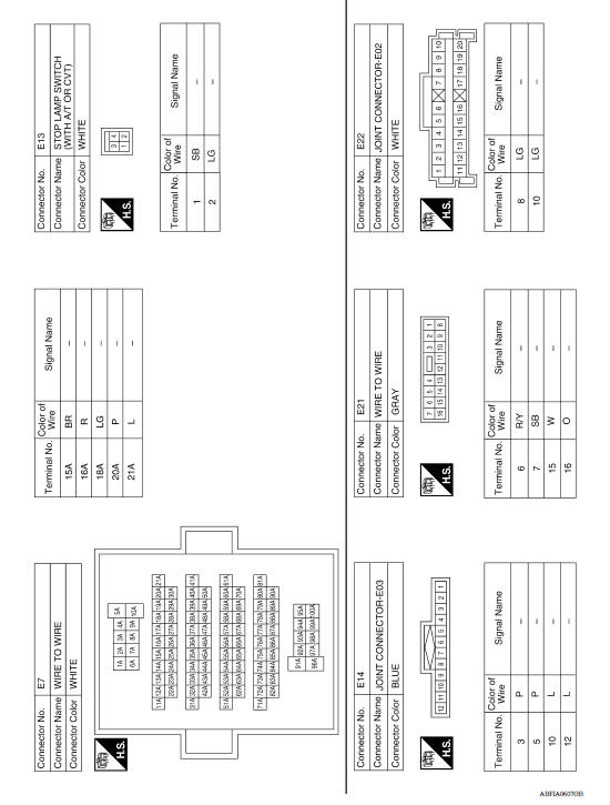
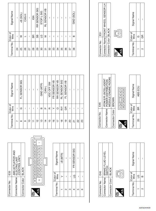
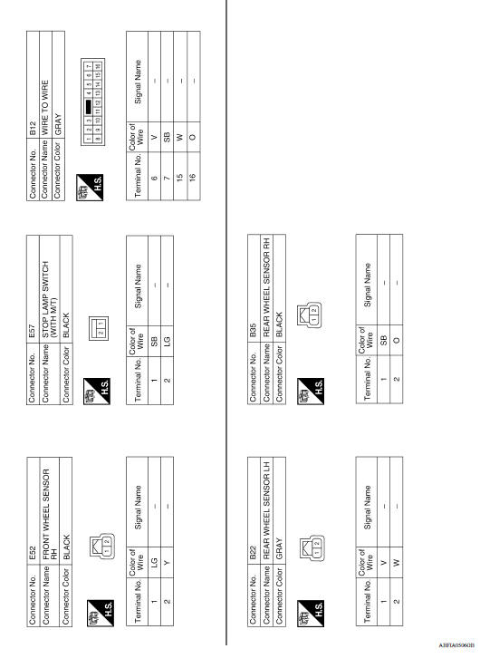
WIRING DIAGRAM
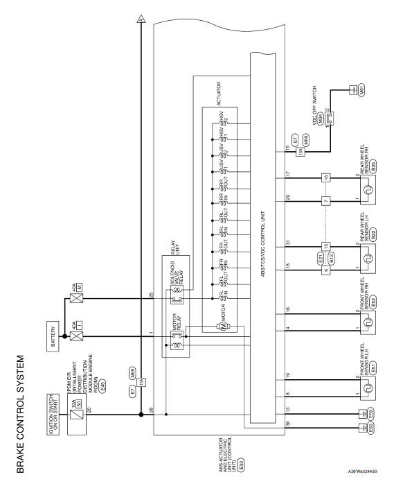
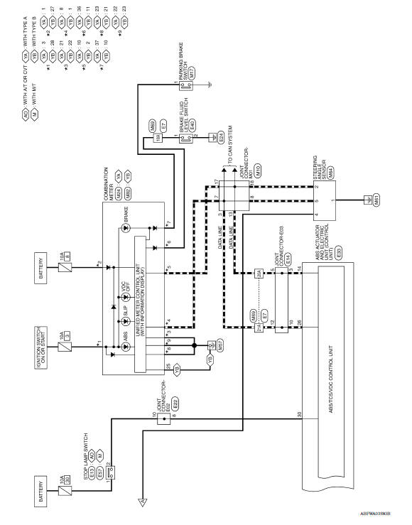
BRAKE CONTROL SYSTEM
Wiring Diagram
BASIC INSPECTION
 Diagnosis system [abs actuator
and electric unit (control unit)]
Diagnosis system [abs actuator
and electric unit (control unit)]
CONSULT Function (ABS) APPLICATION ITEMS CONSULT can display each diagnostic item using the following direct diagnostic modes. ECU IDENTIFICATION ABS actuator and electric uni ...
Diagnosis and repair work flow
Work Flow OVERALL SEQUENCE DETAILED FLOW 1.COLLECT INFORMATION FROM THE CUSTOMER Get detailed information from the customer about the symptom (the condition and the environment when the in ...
Other materials:
Engine stand setting
Setting
NOTE:
The following procedures explain how to disassemble the engine with the engine
stand fastened to the bell
housing. Some steps may be different if using a different type of engine stand.
1. Install engine to engine stand:
a. Rem ...
A/T Shift lock system
A/T Shift lock system : component parts
location
1 Stop lamp switch. 2 Shift lock release lever. 3 Park position switch.
4 Shift lock solenoid.
A/T Shift lock system : component description
...
Categories
- Manuals Home
- Nissan Versa Owners Manual
- Nissan Versa Service Manual
- Video Guides
- Questions & Answers
- External Resources
- Latest Updates
- Most Popular
- Sitemap
- Search the site
- Privacy Policy
- Contact Us

0.0062