Nissan Versa (N17): Front air control
Exploded View
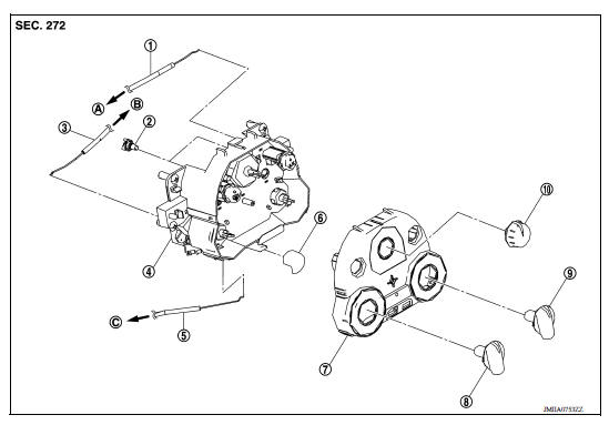
1. Mode door cable 2. Illumination bulb 3. Air mix door cable 4. Front air control 5. Intake door cable 6. Intake door lever knob 7. Control panel bezel 8. Mode dial 9. Temperature dial 10. Fan control dial A. To mode door link B. To air mix door link C. To intake door link
Removal and Installation
REMOVAL
- Remove A/C finisher. Refer to IP "Removal and Installation".
- Remove the air mix door cable from the A/C unit assembly. Refer to HAC "AIR MIX DOOR CABLE : Removal and Installation".
- Remove the mode door cable from the A/C unit assembly. Refer to HAC "MODE DOOR CABLE : Removal and Installation".
- Remove the intake door cable from the A/C unit assembly. Refer to HAC "INTAKE DOOR CABLE : Removal and Installation".
- Remove the front air control screws.
- Remove the front air control.
INSTALLATION
Installation is in the reverse order of removal.
 Compressor does not operate
Description SYMPTOM Compressor does not operate. Diagnosis Procedure NOTE: Perform self-diagnosis with CONSULT before performing symptom diagnosis. If any malfunction result or DTC is d ...
Refrigerant pressure sensor
Removal and Installation for Refrigerant Pressure Sensor REMOVAL CAUTION: Do not damage the condenser fins. Perform lubricant return operation before each refrigeration system disassembly. ...
Other materials:
Rear window defroster switch
To defrost the rear window glass, start the engine
and push the rear window defroster switch on.
The rear window defroster indicator light on the
switch comes on. Push the switch again to turn
the defroster off.
The rear window defroster automatically turns off
after approximately 15 m ...
P0506 ISC system
Description
The ECM controls the engine idle speed to a specified level through the fine
adjustment of the air, which is let
into the intake manifold, by operating the electric throttle control actuator.
The operating of the throttle valve is
varied to allow for optimum control of the engine ...
Categories
- Manuals Home
- Nissan Versa Owners Manual
- Nissan Versa Service Manual
- Video Guides
- Questions & Answers
- External Resources
- Latest Updates
- Most Popular
- Sitemap
- Search the site
- Privacy Policy
- Contact Us

0.0049