
Nissan Versa (N17): Hood hinge
HOOD HINGE : Removal and Installation
REMOVAL
- Remove hood assembly. Refer to DLK "HOOD ASSEMBLY : Removal and Installation".
- Remove hood support rod and grommet. Refer to DLK"HOOD SUPPORT ROD : Removal and Installation".
- Remove front fender. Refer to DLK "FRONT FENDER : Removal and Installation".
- Remove hood hinge bolts and remove hood hinge.
INSTALLATION
Installation is in the reverse order of removal.
CAUTION:
- Check hood hinge rotating point for poor lubrication. If necessary, apply a suitable multi-purpose grease.
- Perform hood fitting adjustment procedure. Refer to DLK "HOOD ASSEMBLY : Adjustment".
- After adjusting, apply touch-up paint (body color) onto the head of hood hinge bolts and nuts.
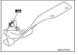
HOOD SUPPORT ROD
HOOD SUPPORT ROD : Removal and Installation
REMOVAL
- Support hood assembly using a suitable tool.
WARNING: Bodily injury may occur if hood assembly is not supported properly when removing hood support rod.
- Rotate and remove hood support rod from grommet.
- Release tab and remove grommet from hood hinge, if necessary.
INSTALLATION
Installation is in the reverse order of removal.
RADIATOR CORE SUPPORT
Exploded View
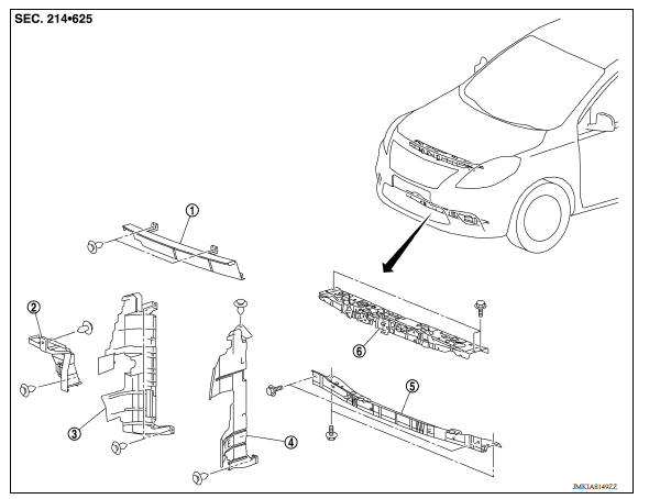
1. Radiator upper seal 2. Condenser side seal 3. Radiator side seal (RH) 4. Radiator side seal (LH) 5. Radiator core support lower 6. Radiator core support upper
 Hood assembly
Radiator core support upper
RADIATOR CORE SUPPORT UPPER : Removal and Installation RADIATOR CORE SUPPORT UPPER Removal 1. Remove ground harness bolt (A). 2. Remove horn. Refer to HRN "Removal and Installation" ...
Other materials:
P1212 TCS communication line
Description
This CAN communication line is used to control the smooth engine operation
during the TCS operation. Pulse
signals are exchanged between ECM and "ABS actuator and electric unit (control
unit)".
Be sure to erase the malfunction information such as DTC not only for "ABS
actuat ...
U1000 CAN Comm
DTC Logic
DTC DETECTION LOGIC
NOTE:
U1000 can be set if a module harness was disconnected and reconnected, perhaps
during a repair. Confirm
that there are actual CAN diagnostic symptoms and a present DTC by performing
the Self Diagnostic Result
procedure. ...
Categories
- Manuals Home
- Nissan Versa Owners Manual
- Nissan Versa Service Manual
- Video Guides
- Questions & Answers
- External Resources
- Latest Updates
- Most Popular
- Sitemap
- Search the site
- Privacy Policy
- Contact Us

0.0273