Nissan Versa (N17): U1000 CAN Comm
DTC Logic
DTC DETECTION LOGIC
NOTE:
U1000 can be set if a module harness was disconnected and reconnected, perhaps
during a repair. Confirm
that there are actual CAN diagnostic symptoms and a present DTC by performing
the Self Diagnostic Result
procedure. 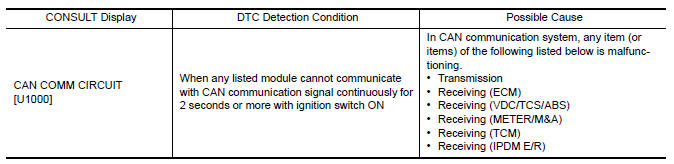
Diagnosis Procedure
1. PERFORM SELF DIAGNOSTIC RESULT
1. Turn ignition switch ON and wait for 2 second or more.
2. Check "SELF- DIAG RESULTS".
Is "CAN COMM CIRCUIT" displayed?
YES >> Perform CAN Diagnosis as described in DIAGNOSIS section of CONSULT Operation Manual.
NO >> Refer to GI "Intermittent Incident".
 Inspection and adjustment
ADDITIONAL SERVICE WHEN REPLACING CONTROL UNIT ADDITIONAL SERVICE WHEN REPLACING CONTROL UNIT : Special Repair Requirement Refer to the CONSULT Immobilizer mode and follow the on-screen instruct ...
U1010 Control unit (CAN)
DTC Logic DTC DETECTION LOGIC Diagnosis Procedure 1.REPLACE BCM When DTC "U1010" is detected, replace BCM. >> Replace BC ...
Other materials:
Nissan vehicle immobilizer systemnats
symptoms
Symptom Table
NOTE:
Before performing the diagnosis in the following table, check "SEC
"Work Flow"".
Check that vehicle is under the condition shown in "Conditions of
vehicle" before starting diagnosis, and
check each symptom.
If the following symptoms are detected, chec ...
Front regulator
Exploded View
1. Front door panel 2. Front door lower sash (front) 3. Front door glass run
4. Front door sealing screen 5. Front door power window motor 6. Front door
regulator
7. Front door glass 8. Front door lower sash (rear) 9. Regulator seal (manual
window)
10. Snap pin (manual wind ...
Categories
- Manuals Home
- Nissan Versa Owners Manual
- Nissan Versa Service Manual
- Video Guides
- Questions & Answers
- External Resources
- Latest Updates
- Most Popular
- Sitemap
- Search the site
- Privacy Policy
- Contact Us

0.0048