Nissan Versa (N17): Main line between IPDM-E and DLC circuit
Diagnosis Procedure
1.CHECK CONNECTOR
1. Turn the ignition switch OFF.
2. Disconnect the battery cable from the negative terminal.
3. Check the following terminals and connectors for damage, bend and loose connection (connector side and harness side).
- Harness connector E7
- Harness connector M69
Is the inspection result normal?
YES >> GO TO 2.
NO >> Repair the terminal and connector.
2.CHECK HARNESS CONTINUITY (OPEN CIRCUIT)
1. Disconnect the following harness connectors.
- IPDM E/R
- Harness connectors E7 and M69
2. Check the continuity between the IPDM E/R harness connector and the
harness connector.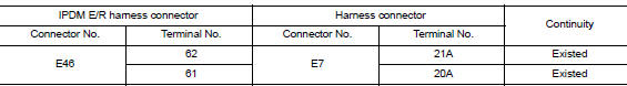
Is the inspection result normal?
YES >> GO TO 3.
NO >> Repair the main line between the IPDM E/R and the harness connector E7.
3.CHECK HARNESS CONTINUITY (OPEN CIRCUIT)
Check the continuity between the harness connector and the data link
connector.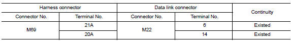
Is the inspection result normal?
YES (Present error)>>Check CAN system type decision again.
YES (Past error)>>Error was detected in the main line between the IPDM E/R and the data link connector.
NO >> Repair the main line between the harness connector M69 and the data link connector.
 CAN Communication circuit
Diagnosis Procedure 1.CONNECTOR INSPECTION 1. Turn the ignition switch OFF. 2. Disconnect the battery cable from the negative terminal. 3. Disconnect all the unit connectors on CAN communication ...
ECM Branch line circuit
Diagnosis Procedure 1.CHECK CONNECTOR 1. Turn the ignition switch OFF. 2. Disconnect the battery cable from the negative terminal. 3. Check the terminals and connectors of the ECM for damage, be ...
Other materials:
Sun visors
1. To block glare from the front, swing down
the sun visor 1 .
2. To block glare from the side, remove the sun
visor from the center mount and swing the
visor to the side 2 .
3. Slide the extension 3 sun visor in or out as
needed.
CAUTION
Do not store the sun visor before returning
...
Cold weather driving
Freeing a frozen door lock
To prevent a door lock from freezing, apply deicer
through the key hole. If the lock becomes
frozen, heat the key before inserting it into the key
hole, or use the remote keyless entry key fob or
the NISSAN Intelligent Key.
Antifreeze
In the winter when it is antic ...
Categories
- Manuals Home
- Nissan Versa Owners Manual
- Nissan Versa Service Manual
- Video Guides
- Questions & Answers
- External Resources
- Latest Updates
- Most Popular
- Sitemap
- Search the site
- Privacy Policy
- Contact Us

0.006