Nissan Versa (N17): CAN Communication circuit
Diagnosis Procedure
1.CONNECTOR INSPECTION
1. Turn the ignition switch OFF.
2. Disconnect the battery cable from the negative terminal.
3. Disconnect all the unit connectors on CAN communication system.
4. Check terminals and connectors for damage, bend and loose connection.
Is the inspection result normal?
YES >> GO TO 2.
NO >> Repair the terminal and connector.
2.CHECK HARNESS CONTINUITY (SHORT CIRCUIT)
Check the continuity between the data link connector terminals.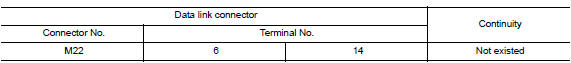
Is the inspection result normal?
YES >> GO TO 3.
NO >> Check the harness and repair the root cause.
3.CHECK HARNESS CONTINUITY (SHORT CIRCUIT)
Check the continuity between the data link connector and the ground.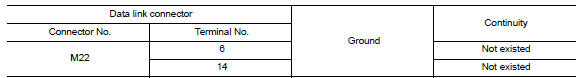
Is the inspection result normal?
YES >> GO TO 4.
NO >> Check the harness and repair the root cause.
4.CHECK ECM AND BCM TERMINATION CIRCUIT
1. Remove the ECM and the BCM.
2. Check the resistance between the ECM terminals.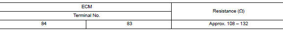
3. Check the resistance between the BCM terminals.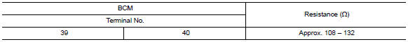
Is the measurement value within the specification?
YES >> GO TO 5.
NO >> Replace the ECM and/or the BCM.
5.CHECK SYMPTOM
Connect all the connectors. Check if the symptoms described in the "Symptom (Results from interview with customer)" are reproduced.
Inspection result
Reproduced>>GO TO 6.
Non-reproduced>>Start the diagnosis again. Follow the trouble diagnosis procedure when past error is detected.
6.CHECK UNIT REPRODUCTION
Perform the reproduction test as per the following procedure for each unit.
1. Turn the ignition switch OFF.
2. Disconnect the battery cable from the negative terminal.
3. Disconnect one of the unit connectors of CAN communication system.
NOTE: ECM and BCM have a termination circuit. Check other units first.
4. Connect the battery cable to the negative terminal. Check if the symptoms described in the "Symptom (Results from interview with customer)" are reproduced.
NOTE: Although unit-related error symptoms occur, do not confuse them with other symptoms.
Inspection result
Reproduced>>Connect the connector. Check other units as per the above procedure.
Non-reproduced>>Replace the unit whose connector was disconnected.
CAN SYSTEM (TYPE 3)
DTC/CIRCUIT DIAGNOSIS
 BCM Branch line circuit
Diagnosis Procedure 1.CHECK CONNECTOR 1. Turn the ignition switch OFF. 2. Disconnect the battery cable from the negative terminal. 3. Check the terminals and connectors of the BCM for damage, bend ...
Main line between IPDM-E and DLC
circuit
Diagnosis Procedure 1.CHECK CONNECTOR 1. Turn the ignition switch OFF. 2. Disconnect the battery cable from the negative terminal. 3. Check the following terminals and connectors for damage, ben ...
Other materials:
Road wheel tire assembly
Adjustment
BALANCING WHEELS (ADHESIVE WEIGHT TYPE)
Preparation Before Adjustment
Remove inner and outer balance weights from the road wheel. Using releasing
agent, remove double-faced
adhesive tape from the road wheel.
CAUTION:
Be careful not scratch the road wheel during removal.
Afte ...
High-pressure flexible hose
Removal and Installation
CAUTION:
Perform oil return operation before each refrigeration system disassembly.
However, if a large amount
of refrigerant or oil is detected, do not perform oil return operation. Refer to
HA "Perform Oil
Return Operation".
REMOVAL
Use refrigerant ...
Categories
- Manuals Home
- Nissan Versa Owners Manual
- Nissan Versa Service Manual
- Video Guides
- Questions & Answers
- External Resources
- Latest Updates
- Most Popular
- Sitemap
- Search the site
- Privacy Policy
- Contact Us

0.0047