Nissan Versa (N17): BCM Branch line circuit
Diagnosis Procedure
1.CHECK CONNECTOR
1. Turn the ignition switch OFF.
2. Disconnect the battery cable from the negative terminal.
3. Check the terminals and connectors of the BCM for damage, bend and loose connection (unit side and connector side).
Is the inspection result normal?
YES >> GO TO 2.
NO >> Repair the terminal and connector.
2.CHECK HARNESS FOR OPEN CIRCUIT
1. Disconnect the connector of BCM.
2. Check the resistance between the BCM harness connector terminals.
- Models with Intelligent Key system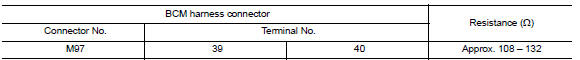
- Models without Intelligent Key system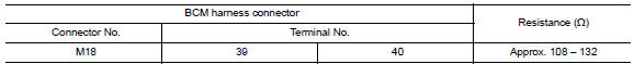
Is the measurement value within the specification?
YES >> GO TO 3.
NO >> Repair the BCM branch line.
3.CHECK POWER SUPPLY AND GROUND CIRCUIT
Check the power supply and the ground circuit of the BCM. Refer to the following.
- Models with Intelligent Key system: BCS "Diagnosis Procedure"
- Models without Intelligent Key system: BCS "Diagnosis Procedure"
Is the inspection result normal?
YES (Present error)>>Replace the BCM. Refer to the following.
- Models with Intelligent Key system: BCS "Removal and Installation"
- Models without Intelligent Key system: BCS "Removal and Installation"
YES (Past error)>>Error was detected in the BCM branch line.
NO >> Repair the power supply and the ground circuit.
 STRG Branch line circuit
Diagnosis Procedure 1.CHECK CONNECTOR 1. Turn the ignition switch OFF. 2. Disconnect the battery cable from the negative terminal. 3. Check the terminals and connectors of the steering angle sen ...
CAN Communication circuit
Diagnosis Procedure 1.CONNECTOR INSPECTION 1. Turn the ignition switch OFF. 2. Disconnect the battery cable from the negative terminal. 3. Disconnect all the unit connectors on CAN communication ...
Other materials:
Maintenance precautions
When performing any inspection or maintenance
work on your vehicle, always take care to prevent
serious accidental injury to yourself or damage to
the vehicle. The following are general precautions
which should be closely observed.
WARNING
Park the vehicle on a level surface, apply
the pa ...
Reporting safety defects
For USA
If you believe that your vehicle has a defect
which could cause a crash or could
cause injury or death, you should immediately
inform the National Highway Traffic
Safety Administration (NHTSA) in addition
to notifying NISSAN.
If NHTSA receives similar complaints, it
may open an inv ...
Categories
- Manuals Home
- Nissan Versa Owners Manual
- Nissan Versa Service Manual
- Video Guides
- Questions & Answers
- External Resources
- Latest Updates
- Most Popular
- Sitemap
- Search the site
- Privacy Policy
- Contact Us

0.005