Nissan Versa (N17): Microphone signal circuit
Diagnosis Procedure
Regarding Wiring Diagram information, refer to AV "Wiring Diagram".
1.CHECK HARNESS BETWEEN BLUETOOTH CONTROL UNIT AND MICROPHONE
1. Turn ignition switch OFF.
2. Disconnect Bluetooth control unit connector B33 and microphone connector R15.
3. Check continuity between Bluetooth control unit connector B33 and
microphone connector R15.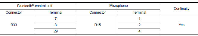
4. Check continuity between Bluetooth control unit connector B33 and ground.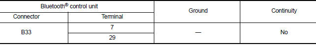
Are continuity results as specified?
YES >> GO TO 2
NO >> Repair harness or connectors.
2.CHECK MICROPHONE POWER SUPPLY
1. Connect Bluetooth control unit connector B33 and microphone connector R15.
2. Turn ignition switch ON.
3. Check voltage between microphone connector R15 and ground.
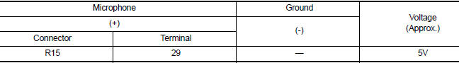
Is the voltage reading as specified?
YES >> GO TO 3
NO >> Replace Bluetooth control unit. Refer to AV"Removal and Installation".
3.CHECK MICROPHONE SIGNAL
Check signal between terminals of Bluetooth control unit connector B33.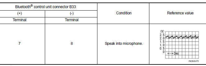
Were voltage readings as specified?
YES >> Replace Bluetooth control unit. Refer to AV "Removal and Installation".
NO >> Replace microphone. Refer to AV "Removal and Installation".
 Bluetooth control signal circuit
Diagnosis Procedure Regarding Wiring Diagram information, refer to AV "Wiring Diagram". 1.CHECK CONTROL SIGNAL CIRCUIT CONTINUITY 1. Turn ignition switch OFF. 2. Disconnect Bluetooth con ...
Steering switch
Diagnosis Procedure Regarding Wiring Diagram information, refer to AV "Wiring Diagram". 1.CHECK STEERING WHEEL AUDIO CONTROL SWITCH RESISTANCE 1. Turn ignition switch OFF. 2. Disconnect ...
Other materials:
U0155 Lost communication (IPC)
DTC Logic
DTC DETECTION LOGIC
DTC
Trouble diagnosis name
DTC detection condition
Possible causes
U0155
Lost Communication With Instrument
Panel Cluster (IPC)
Control Module
When the ignition switch is ON,
TCM is unable to receive the
CAN communications ...
EPS Control unit
Exploded View
1. Steering column assembly 2. Bracket 3. EPS control unit
Removal and Installation
REMOVAL
Perform a CPU memory erase on the EPS with CONSULT before removal.
CAUTION:
Disconnect battery negative terminal before continuing.
Do not shock EPS control unit, e.g. ...
Categories
- Manuals Home
- Nissan Versa Owners Manual
- Nissan Versa Service Manual
- Video Guides
- Questions & Answers
- External Resources
- Latest Updates
- Most Popular
- Sitemap
- Search the site
- Privacy Policy
- Contact Us

0.0047