Nissan Versa (N17): Steering switch
Diagnosis Procedure
Regarding Wiring Diagram information, refer to AV "Wiring Diagram".
1.CHECK STEERING WHEEL AUDIO CONTROL SWITCH RESISTANCE
1. Turn ignition switch OFF.
2. Disconnect combination switch connector M88.
3. Check resistance between the terminals of combination switch connector
M88.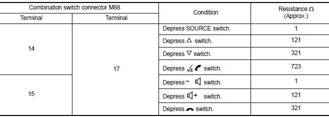
Is the inspection result normal?
YES >> GO TO 2.
NO >> Replace steering switches. Refer to AV "Removal and Installation".
2.CHECK HARNESS BETWEEN BLUETOOTH CONTROL UNIT AND COMBINATION SWITCH
1. Disconnect Bluetooth control unit connector B33 and combination switch connector M30.
2. Check continuity between Bluetooth control unit connector B33 and
combination switch connector M30.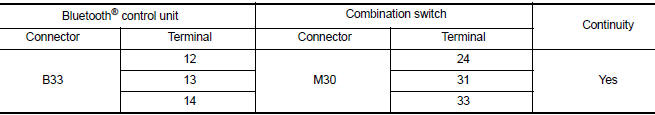
3. Check continuity between Bluetooth control unit connector B33 and ground.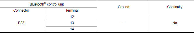
Is the inspection result normal?
YES >> GO TO 3.
NO >> Repair or replace harness or connectors.
3.CHECK COMBINATION SWITCH
Check continuity between combination switch connectors M88 and M30.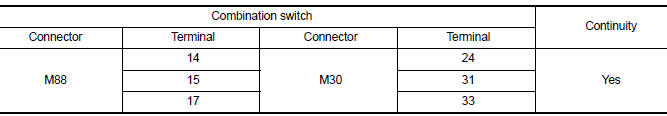
Is the inspection result normal?
YES >> GO TO 4.
NO >> Replace spiral cable. Refer to SR "Removal and Installation".
4.CHECK HARNESS BETWEEN BLUETOOTH CONTROL UNIT AND AUDIO UNIT
1. Disconnect audio unit connector M44.
2. Check continuity between Bluetooth control unit connector B33 and audio
unit connector M46.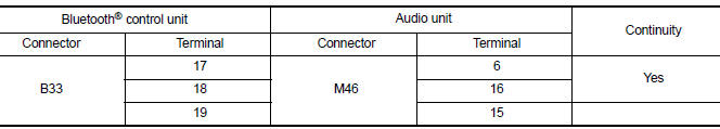
3. Check continuity between Bluetooth control unit connector B33 and ground.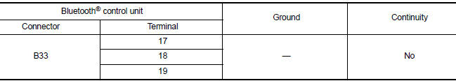
Is the inspection result normal?
YES >> Replace audio unit. Refer to AV "Removal and Installation".
NO >> Repair or replace harness or connectors.
 Microphone signal circuit
Diagnosis Procedure Regarding Wiring Diagram information, refer to AV "Wiring Diagram". 1.CHECK HARNESS BETWEEN BLUETOOTH CONTROL UNIT AND MICROPHONE 1. Turn ignition switch OFF. 2. Di ...
USB Connector
Diagnosis Procedure Regarding Wiring Diagram information, refer to AV "Wiring Diagram". 1.CHECK USB INTERFACE HARNESS CONTINUITY 1. Turn ignition switch OFF. 2. Disconnect audio unit c ...
Other materials:
P0712 Transmission fluid temperature
sensor A
DTC Logic
DTC DETECTION LOGIC
DTC
Trouble diagnosis name
DTC detection condition
Possible causes
P0712
Transmission Fluid Temperature
Sensor A Circuit Low
The CVT fluid temperature identified by the
TCM is 180C (356F) or more continuously
for 5 seconds or ...
Oil pan
Exploded View
1. Transaxle assembly 2. Oil pan gasket 3. Magnet
4. Oil pan 5. Overflow tube 6. Drain plug gasket
7. Drain plug 8. Oil pan fitting bolt
Removal and Installation
REMOVAL
Remove the drain plug and overflow tube, and then drain the CVT fluid.WARNING:
CVT fluid can splash ...
Categories
- Manuals Home
- Nissan Versa Owners Manual
- Nissan Versa Service Manual
- Video Guides
- Questions & Answers
- External Resources
- Latest Updates
- Most Popular
- Sitemap
- Search the site
- Privacy Policy
- Contact Us

0.0078