Nissan Versa (N17): P0181 FTT sensor
DTC Logic
DTC DETECTION LOGIC
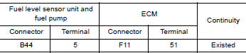
| DTC No. | Trouble diagnosis name (Trouble diagnosis content) | DTC detecting condition | Possible cause | |
| P0181 | FTT SENSOR [Fuel tank temperature (FTT) sensor circuit range/performance] | A | Rationally incorrect voltage from the sensor is sent to ECM, compared with the voltage signals from ECT sensor and intake air temperature sensor. |
|
| B | The comparison result of signals transmitted to ECM from each temperature sensor (IAT sensor, ECT sensor, EOT sensor, and FTT sensor) shows that the voltage signal of the FTT sensor is higher/lower than that of other temperature sensors when the engine is started with its cold state. |
|
||
DTC CONFIRMATION PROCEDURE
1.INSPECTION START
Is it necessary to erase permanent DTC?
YES >> GO TO 7.
NO >> GO TO 2.
2.PRECONDITIONING
If DTC CONFIRMATION PROCEDURE has been previously conducted, always perform the following procedure before conducting the next test.
- Turn ignition switch OFF and wait at least 10 seconds.
- Turn ignition switch ON.
- Turn ignition switch OFF and wait at least 10 seconds.
>> GO TO 3.
3.PERFORM DTC CONFIRMATION PROCEDURE FOR MALFUNCTION AI
- Turn ignition switch ON and wait at least 10 seconds.
- Check 1st trip DTC.
Is 1st trip DTC detected?
YES >> Proceed to EC, "Diagnosis Procedure".
NO >> GO TO 4.
4.CHECK ENGINE COOLANT TEMPERATURE
 With CONSULT
- Select "COOLAN TEMP/S" in "DATA MONITOR" of "ENGINE" using CONSULT.
- Check "COOLAN TEMP/S" value.
 With GST
Follow the procedure "With CONSULT" above.
"COOLAN TEMP/S" less than 60C (140F)?
YES >> INSPECTION END
NO >> GO TO 5.
5.PERFORM DTC CONFIRMATION PROCEDURE FOR MALFUNCTION AII
With CONSULT
- Cool engine down until "COOLAN TEMP/S" is less than 60C (140F).
- Wait at least 10 seconds.
- Check 1st trip DTC.
With GST
Follow the procedure "With CONSULT" above.
Is 1st trip DTC detected?
YES >> Proceed to EC, "Diagnosis Procedure".
NO >> GO TO 6.
6.PERFORM COMPONENT FUNCTION CHECK (FOR MALFUNCTION B)
Perform component function check. Refer to EC, "Component Function Check".
NOTE: Use the component function check to check the overall function of the FTT sensor circuit. During this check, a 1st trip DTC might not be confirmed.
Is the inspection result normal?
YES >> INSPECTION END
NO >> Proceed to EC, "Diagnosis Procedure".
7.PRECONDITIONING
If DTC CONFIRMATION PROCEDURE has been previously conducted, always perform the following procedure before conducting the next test.
- Turn ignition switch OFF and wait at least 10 seconds.
- Turn ignition switch ON.
- Turn ignition switch OFF and wait at least 10 seconds.
TESTING CONDITION:
- Before performing the following procedure, do not add fuel.
- Before performing the following procedure, check that fuel level is between 1/4 and 4/4.
- Before performing the following procedure, confirm that battery voltage is 11 V or more at idle.
>> GO TO 8.
8.PERFORM DTC CONFIRMATION PROCEDURE B
- Start engine and let it idle for 60 minutes.
- Move the vehicle to a cool place.
NOTE: Cool the vehicle in an environment of ambient air temperature between −10C (14F) and 35C (95F).
3. Turn ignition switch OFF and soak the vehicle for 12 hours.
CAUTION: Never turn ignition switch ON during soaking.
NOTE: The vehicle must be cooled with the food open.
4. Start engine and let it idle for 5 minutes or more.
CAUTION: Never turn ignition switch OFF during idling.
5. Check 1st trip DTC.
Is 1st trip DTC detected?
YES >> Proceed to EC, "Diagnosis Procedure".
NO >> INSPECTION END
Component Function Check
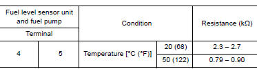
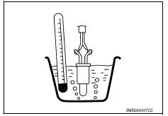
1.CHECK FUEL TANK TEMPERATURE (FTT) SENSOR
- Turn ignition switch OFF.
- Disconnect fuel level sensor unit and fuel pump harness connector.
- Remove fuel level sensor unit. Refer to FL, "Removal and Installation".
- Check resistance between fuel level sensor unit and fuel pump
terminals by heating with hot water as shown in the figure.
Is the inspection result normal?
YES >> Check intermittent incident. Refer to GI, "Intermittent Incident".
NO >> Proceed to EC, "Diagnosis Procedure".
Diagnosis Procedure
1.INSPECTION START
Confirm the detected malfunction (A or B). Refer to EC, "DTC Logic".
Which malfunction is detected?
A >> GO TO 2.
B >> GO TO 6.
2.CHECK DTC WITH COMBINATION METER
Check DTC with combination meter. Refer to MWI, "CONSULT Function" (TYPE A) or MWI, "CONSULT Function" (TYPE B). Check the vehicle type to confirm the service information in MWI section. Refer to MWI, "Information".
Is the inspection result normal?
YES >> GO TO 3.
NO >> Proceed to MWI, "Component Function Check" (TYPE A) or MWI, "Component Function Check" (TYPE B).
3.CHECK FUEL TANK TEMPERATURE (FTT) SENSOR POWER
- Turn ignition switch OFF.
- Disconnect fuel level sensor unit and fuel pump harness connector.
- Turn ignition switch ON.
- Check the voltage between fuel level sensor unit and fuel pump harness
connector and ground.
Is the inspection result normal?
YES >> GO TO 5.
NO >> GO TO 4.
4.CHECK FUEL TANK TEMPERATURE (FTT) SENSOR POWER SUPPLY CIRCUIT
- Turn ignition switch OFF.
- Disconnect ECM harness connector.
- Check the continuity between fuel level sensor unit and fuel pump
harness connector and ECM harness
connector.
4. Also check harness for short to ground and to power.
Is the inspection result normal?
YES >> Perform the trouble diagnosis for power supply circuit.
NO >> Repair or replace errordetected parts.
5.CHECK FTT SENSOR GROUND CIRCUIT
- Turn ignition switch OFF.
- Disconnect ECM harness connector.
- Check the continuity between fuel level sensor unit and fuel pump
harness connector and ECM harness
connector.
4. Also check harness for short to power.
Is the inspection result normal?
YES >> GO TO 6.
NO >> Repair or replace errordetected parts.
6.CHECK FUEL TANK TEMPERATURE (FTT) SENSOR
Check the FTT sensor. Refer to EC, "Component Inspection".
Is the inspection result normal?
YES >> Check intermittent incident. Refer to GI, "Intermittent Incident".
NO >> Replace fuel level sensor unit and fuel pump. Refer to FL, "Removal and Installation".
Component Inspection
1.CHECK FUEL TANK TEMPERATURE (FTT) SENSOR
- Turn ignition switch OFF.
- Disconnect fuel level sensor unit and fuel pump harness connector.
- Remove fuel level sensor unit. Refer to FL, "Removal and Installation".
- Check resistance between fuel level sensor unit and fuel pump
terminals by heating with hot water as shown in the figure.
Is the inspection result normal?
YES >> INSPECTION END
NO >> Replace fuel level sensor unit and fuel pump. Refer to FL, "Removal and Installation".
 P0171 fuel injection system function
Other materials:
Towing a trailer
Flat towing
Do not tow a trailer with your vehicle.
Towing your vehicle with all four wheels on the
ground is sometimes called flat towing. This
method is sometimes used when towing a vehicle
behind a recreational vehicle, such as a motor
home.
CAUTION
Failure to follow these guidelines c ...
P0712 Transmission fluid temperature
sensor A
DTC Logic
DTC DETECTION LOGIC
DTC
Trouble diagnosis name
DTC detection condition
Possible causes
P0712
Transmission Fluid Temperature
Sensor A Circuit Low
The CVT fluid temperature identified by the
TCM is 180C (356F) or more continuously
for 5 seconds or ...
Categories
- Manuals Home
- Nissan Versa Owners Manual
- Nissan Versa Service Manual
- Video Guides
- Questions & Answers
- External Resources
- Latest Updates
- Most Popular
- Sitemap
- Search the site
- Privacy Policy
- Contact Us

0.0072