Nissan Versa (N17): Oil
Description
MAINTENANCE OF OIL LEVEL
The compressor oil is circulating in the system together with the refrigerant. It is necessary to fill compressor with oil when replacing A/C system parts or when a large amount of refrigerant leakage is detected. It is important to always maintain oil level within the specified level. Otherwise, the following conditions may occur;
- Insufficient oil amount: Stuck compressor
- Excessive oil amount: Insufficient cooling (caused by insufficient heat exchange)
TYPE : Refer to HA "Oil".
Inspection
If a compressor is malfunctioning (internal noise, insufficient cooling), check the compressor oil.
1.COMPRESSOR OIL JUDGMENT
- Remove the compressor. Refer to HA "Removal and Installation".
- Sample compressor oil and judge based on the figure.
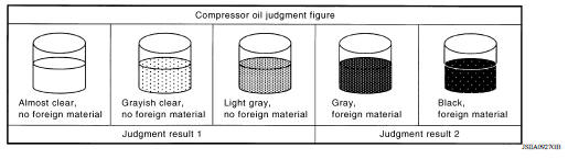
Judgement result 1>>Replace compressor only.
Judgement result 2>>Replace compressor and liquid tank.
Perform Oil Return Operation
CAUTION: If a large amount of refrigerant or oil leakage is detected, do not perform oil return operation.
1. Start the engine and set to the following conditions.
- Engine speed: Idling to 1,200 rpm
- A/C switch: ON
- Fan speed: Maximum speed set
- Intake door position: Recirculation
- Temperature setting: Full cold
- Perform oil return operation for approximately 10 minutes.
- Stop the engine.
- Oil return operation is complete.
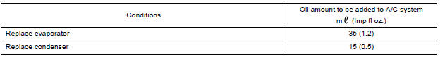
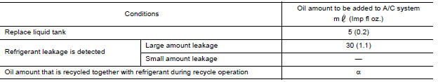
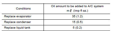
Oil Adjusting Procedure for Components Replacement Except Compressor
Fill with oil for the amount that is calculated according to the following
conditions;
Example: oil amount to be added when replacing evaporator and liquid tank [m
(Imp fl oz.)] = 35 (1.2) + 5
(0.2) + α
Oil Adjusting Procedure for Compressor Replacement
1. Drain oil from removed compressor and measure oil amount.
- Drain oil from high-pressure port (A) and low-pressure port (B) while rotating magnet clutch.
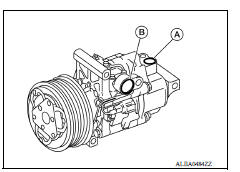
- Measure total amount of oil that is drained from removed compressor.
2. Drain oil from a new compressor that is calculated according to the following conditions;
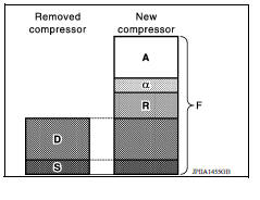
Amount to be drained (A) [m (Imp fl oz.)] = F − (D + S + R + α)
F : Oil amount that a new compressor contains [120 (4.2)]
D : Oil amount that is drained from removed compressor
S : Oil amount that remains inside of removed compressor [20 (0.7)]
R : Oil amount to be added according to components that are removed except compressor
α : Oil amount that is recycled together with refrigerant during recycle operation
CAUTION:
If oil amount that is drained from removed compressor is less than 60 m (2.1 Imp
fl oz.), perform
calculation by setting "D" as 40 m (1.4 Imp fl oz.).
Example: oil amount to be drained from a new compressor when replacing compressor and liquid tank [m (Imp fl oz.)] [D = 60 (2.1), α = 5 (0.2)] 120 (4.2) − [60 (2.1) + 20 (0.7) + 5 (0.2) + 5 (0.2)] = 30 (1.1)
3. Install compressor and check the operation.
 Refrigerant
Description CONNECTION OF SERVICE TOOLS AND EQUIPMENT 1. Shut-off valve 2. A/C service valve 3. Recovery/recycling/recharging equipment 4. Vacuum pump 5. Manifold gauge set 6. Refrigerant con ...
Performance test
Inspection INSPECTION PROCEDURE Connect recovery/recycling/recharging equipment (for HFC-134a) or manifold gauge. Start the engine, and set to the following condition. Test condition&nbs ...
Other materials:
Trunk lid
WARNING
Do not drive with the trunk lid open. This
could allow dangerous exhaust gases
to be drawn into the vehicle. For additional
information, refer to "Exhaust
gas (carbon monoxide)" in the "Starting
and driving" section of this manual.
Closely supervise children when they
are a ...
Oil pump
Exploded View
1. Rear oil seal 2. Oring 3. Oil pan (upper)
4. Oil pump chain tensioner (for oil
pump drive chain)
5. Oil pump drive chain 6. Crankshaft key
7. Crankshaft sprocket 8. Oil pump sprocket 9. Oil pump
10. Oring 11. Oring 12. Oil pan drain plug
13. Drain plug washer 14. Oil pan ( ...
Categories
- Manuals Home
- Nissan Versa Owners Manual
- Nissan Versa Service Manual
- Video Guides
- Questions & Answers
- External Resources
- Latest Updates
- Most Popular
- Sitemap
- Search the site
- Privacy Policy
- Contact Us

0.0063