Nissan Versa (N17): Power supply and ground circuit
Diagnosis Procedure
Regarding Wiring Diagram information, refer to BCS "Wiring Diagram".
1.CHECK FUSES AND FUSIBLE LINK
Check that the following fuses and fusible link are not blown.
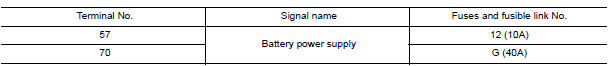
Is the fuse blown?
YES >> Replace the blown fuse or fusible link after repairing the affected circuit.
NO >> GO TO 2.
2.CHECK POWER SUPPLY CIRCUIT
- Disconnect BCM connector M99.
- Check voltage between BCM connector M99 and ground.
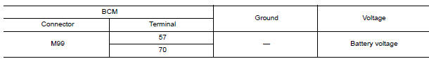
Is the inspection result normal?
YES >> GO TO 3.
NO >> Repair harness or connector.
3.CHECK GROUND CIRCUIT
Check continuity between BCM connector M99 and ground.

Is the inspection result normal?
YES >> Inspection End.
NO >> Repair harness or connector.
 B2628 Outside antenna
Combination meter buzzer
Component Function Check 1.CHECK FUNCTION Select INTELLIGENT KEY of BCM using CONSULT. Select INSIDE BUZZER in ACTIVE TEST mode. Touch Key, Knob or Take Out to check that it works normally. ...
Other materials:
Power window main switch
Removal and Installation
REMOVAL
1. Remove main power window and door lock/unlock switch finisher
assembly using a suitable tool (A).
Pawl
2. Disconnect the harness connector from the main power window and door
lock/unlock switch.
3. Separate main power window and door lock/unlock switch ...
Main line between IPDM-E and DLC
circuit
Diagnosis Procedure
1.CHECK CONNECTOR
1. Turn the ignition switch OFF.
2. Disconnect the battery cable from the negative terminal.
3. Check the following terminals and connectors for damage, bend and loose
connection (connector side
and harness side).
Harness connector E7
Harness conn ...
Categories
- Manuals Home
- Nissan Versa Owners Manual
- Nissan Versa Service Manual
- Video Guides
- Questions & Answers
- External Resources
- Latest Updates
- Most Popular
- Sitemap
- Search the site
- Privacy Policy
- Contact Us

0.0634