Nissan Versa (N17): Power supply and ground circuit
Diagnosis Procedure
Regarding Wiring Diagram information, refer to BCS "Wiring Diagram".
1.CHECK FUSES AND FUSIBLE LINK
Check that the following fuses and fusible link are not blown. 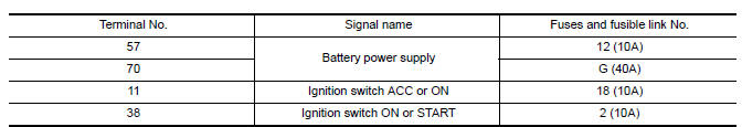
Is the fuse blown?
YES >> Replace the blown fuse or fusible link after repairing the affected circuit.
NO >> GO TO 2.
2.CHECK POWER SUPPLY CIRCUIT
1. Turn ignition switch OFF.
2. Disconnect BCM connectors.
3. Check voltage between BCM connector and ground.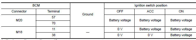
Is the inspection result normal?
YES >> GO TO 3.
NO >> Repair harness or connector.
3.CHECK GROUND CIRCUIT
Check continuity between BCM connector and ground. 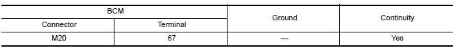
Is the inspection result normal?
YES >> Inspection End.
NO >> Repair harness or connector.
 B2196 Dongle unit
Description BCM performs ID verification between BCM and dongle unit. When verification result is OK, BCM permits cranking. ...
Vehicle security indicator
Description Vehicle security indicator is built in combination meter. NATS (Nissan Anti-Theft System) condition is indicated by blink or illumination of vehicle security indicator. ...
Other materials:
Reporting safety defects
For USA
If you believe that your vehicle has a defect
which could cause a crash or could
cause injury or death, you should immediately
inform the National Highway Traffic
Safety Administration (NHTSA) in addition
to notifying NISSAN.
If NHTSA receives similar complaints, it
may open an inv ...
Final drive
Exploded View
1. Differential side bearing outer race 2. Differential side bearing 3. Final
drive
: Replace the parts as a set.
Disassembly
Remove differential side bearings, using Tool (A) and suitable tool.
Tool number : ST33052000 ( - )
Assembly
Install differential sid ...
Categories
- Manuals Home
- Nissan Versa Owners Manual
- Nissan Versa Service Manual
- Video Guides
- Questions & Answers
- External Resources
- Latest Updates
- Most Popular
- Sitemap
- Search the site
- Privacy Policy
- Contact Us

0.0046