Nissan Versa (N17): Precautions
Precaution for Supplemental Restraint System (SRS) "AIR BAG" and "SEAT BELT PRE-TENSIONER"
The Supplemental Restraint System such as "AIR BAG" and "SEAT BELT PRE-TENSIONER", used along with a front seat belt, helps to reduce the risk or severity of injury to the driver and front passenger for certain types of collision. This system includes seat belt switch inputs and dual stage front air bag modules. The SRS system uses the seat belt switches to determine the front air bag deployment, and may only deploy one front air bag, depending on the severity of a collision and whether the front occupants are belted or unbelted.
Information necessary to service the system safely is included in the SR and SB section of this Service Manual.
WARNING:
- To avoid rendering the SRS inoperative, which could increase the risk of personal injury or death in the event of a collision which would result in air bag inflation, all maintenance must be performed by an authorized NISSAN/INFINITI dealer.
- Improper maintenance, including incorrect removal and installation of the SRS, can lead to personal injury caused by unintentional activation of the system. For removal of Spiral Cable and Air Bag Module, see the SR section.
- Do not use electrical test equipment on any circuit related to the SRS unless instructed to in this Service Manual. SRS wiring harnesses can be identified by yellow and/or orange harnesses or harness connectors
PRECAUTIONS WHEN USING POWER TOOLS (AIR OR ELECTRIC) AND HAMMERS
WARNING:
- When working near the Airbag Diagnosis Sensor Unit or other Airbag System sensors with the Ignition ON or engine running, DO NOT use air or electric power tools or strike near the sensor(s) with a hammer. Heavy vibration could activate the sensor(s) and deploy the air bag(s), possibly causing serious injury.
- When using air or electric power tools or hammers, always switch the Ignition OFF, disconnect the battery and wait at least 3 minutes before performing any service.
Occupant Classification System
Replace occupant classification system control unit as assembly with the passenger seat frame assembly.
Refer to SE "PASSENGER SIDE : Disassembly and Assembly".
Precaution for Work
- When removing or disassembling each component, be careful not to damage or deform it. If a component may be subject to interference, be sure to protect it with a shop cloth.
- When removing (disengaging) components with a screwdriver or similar tool, be sure to wrap the component with a shop cloth or vinyl tape to protect it.
- Protect the removed parts with a shop cloth and prevent them from being dropped.
- Replace a deformed or damaged clip.
- If a part is specified as a non-reusable part, always replace it with a new one.
- Be sure to tighten bolts and nuts securely to the specified torque.
- After installation is complete, be sure to check that each part works properly.
- Follow the steps below to clean components:
- Water soluble dirt:
- Dip a soft cloth into lukewarm water, wring the water out of the cloth and wipe the dirty area.
- Then rub with a soft, dry cloth.
- Oily dirt:
- Dip a soft cloth into lukewarm water with mild detergent (concentration: within 2 to 3%) and wipe the dirty area.
- Then dip a cloth into fresh water, wring the water out of the cloth and wipe the detergent off.
- Then rub with a soft, dry cloth.
- Do not use organic solvent such as thinner, benzene, alcohol or gasoline.
- For genuine leather seats, use a genuine leather seat cleaner.
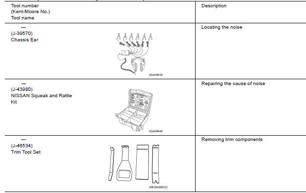
PREPARATION
Special Service Tool
The actual shapes of Kent-Moore tools may differ from those of special service tools illustrated here.
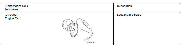
Commercial Service Tool
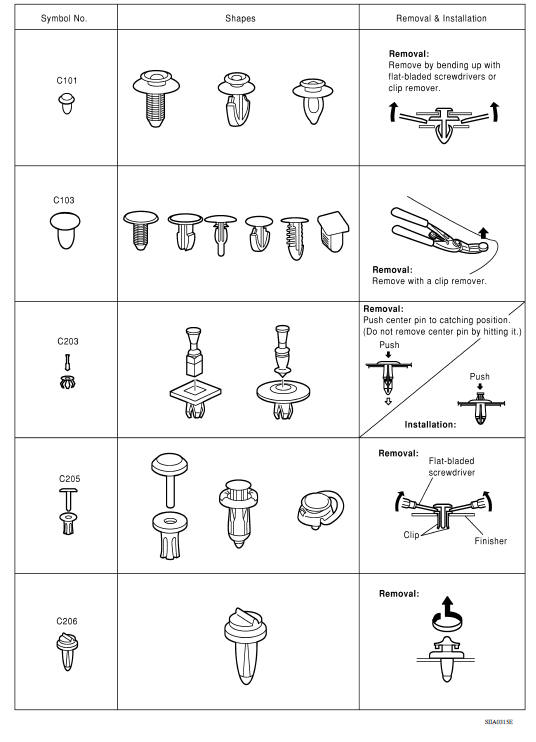
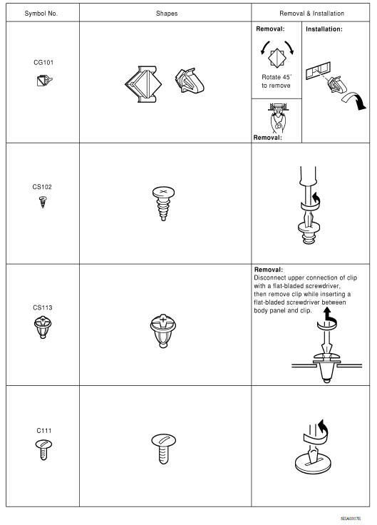
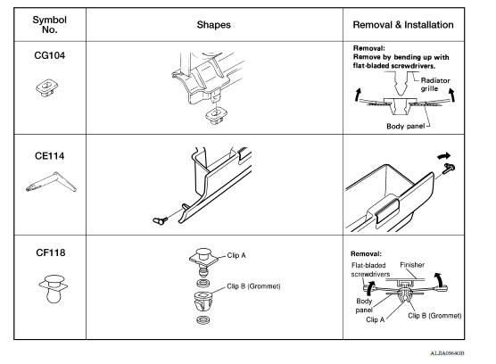
CLIP LIST
Descriptions for Clips
Replace any clips and fasteners which are damaged during removal or installation.
SYMPTOM DIAGNOSIS
 Center console assembly
Exploded View 1. Power socket 2. Center console assembly 3. Center console support 4. USB port and auxiliary jack Disassembly and Assembly DISASSEMBLY Remove the center console assembly. ...

Other materials:
Maintenance under severe operating conditions
The maintenance intervals shown on the preceding pages are for normal
operating conditions. If the vehicle is mainly operated under severe driving
conditions as shown below, more frequent maintenance must be performed on the
following items as shown in the table.
Severe driving conditions
...
U0300 Can communication data
Description
The amount of data transmitted from each control unit is read.
DTC Logic
DTC DETECTION LOGIC
DTC
Trouble diagnosis name
DTC detection condition
Possible causes
U0300
Internal Control Module Software
Incompatibility
When the amount of data transmitt ...
Categories
- Manuals Home
- Nissan Versa Owners Manual
- Nissan Versa Service Manual
- Video Guides
- Questions & Answers
- External Resources
- Latest Updates
- Most Popular
- Sitemap
- Search the site
- Privacy Policy
- Contact Us

0.0055