Nissan Versa (N17): Precautions
Precautions for Trouble Diagnosis
CAUTION: Follow the instructions listed below. Failure to do this may cause damage to parts:
- Never apply 7.0 V or more to the measurement terminal.
- Use a tester with open terminal voltage of 7.0 V or less.
- Turn the ignition switch OFF and disconnect the battery cable from the negative terminal when checking the harness.
Precautions for Harness Repair
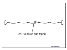
- Solder the repaired area and wrap tape around the soldered area.
NOTE: A fray of twisted lines must be within 110 mm (4.33 in).
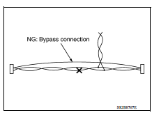
- Bypass connection is never allowed at the repaired area.
NOTE: Bypass connection may cause CAN communication error. The spliced wire becomes separated and the characteristics of twisted line are lost.
- Replace the applicable harness as an assembly if error is detected on the shield lines of CAN communication line.
SYSTEM DESCRIPTION
 Combination switch
Exploded View 1. Combination switch 2. Combination switch harness connector Front Removal and Installation 1. Remove the steering wheel. Refer to ST "Removal and Installation". 2. Re ...
System
CAN COMMUNICATION SYSTEM CAN COMMUNICATION SYSTEM : System Description CAN (Controller Area Network) is a serial communication line for real time application. It is an on-vehicle multiplex commun ...
Other materials:
Continuously Variable Transmission (CVT) fluid (if so equipped)
CAUTION
NISSAN recommends using Genuine
NISSAN CVT Fluid NS-3 (or equivalent)
ONLY in NISSAN CVTs. Do not mix with
other fluids.
Do not use Automatic transmission
fluid (ATF) or Manual transmission fluid
in a NISSAN CVT, as it may damage the
CVT. Damage caused by the use of fluids
...
Adjustment of steering angle sensor
neutral position
Description
Refer to the table below to determine if adjustment of steering angle sensor
neutral position is required.
Work Procedure
ADJUSTMENT OF STEERING ANGLE SENSOR NEUTRAL POSITION
CAUTION:
To adjust neutral position of steering angle sensor, make sure to use CONSULT.
(Adjustme ...
Categories
- Manuals Home
- Nissan Versa Owners Manual
- Nissan Versa Service Manual
- Video Guides
- Questions & Answers
- External Resources
- Latest Updates
- Most Popular
- Sitemap
- Search the site
- Privacy Policy
- Contact Us

0.0056