Nissan Versa (N17): Spark plug
SPARK PLUG : Exploded View

1. Ignition coil 2. Spark plug
SPARK PLUG : Removal and Installation
REMOVAL
1. Remove ignition coil. Refer to EM "Removal and Installation".
CAUTION: Do not drop or shock ignition coil.
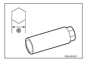
2. Remove spark plug using a suitable tool.
Diameter (a) : 14 mm (0.55 in)
CAUTION: Do not drop or shock spark plug.
INSPECTION AFTER REMOVAL
CAUTION: Do not use a wire brush for cleaning.
- If the spark plug tip is covered with carbon, a spark plug cleaner may be used.
Cleaner air pressure : Less than 588 kPa (6 kg/cm2, 85 psi)
Cleaning time : Less than 20 seconds
- Checking and adjusting spark plug gap is not required between change intervals. Do not adjust the gap; replace the spark plug as necessary if out of specification.
INSTALLATION
Installation is in the reverse order of removal.
CAUTION:
Do not drop or shock the spark plug.
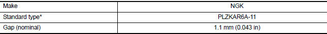
*: Always check with the Parts Department for the latest parts information.
EVAP VAPOR LINES
EVAP VAPOR LINES : Inspection
1. Visually inspect EVAP vapor lines for improper attachment and for cracks, damage, loose connections, chafing and deterioration.
2. Inspect fuel tank filler cap vacuum relief valve for clogging, sticking, etc. Refer to FL "Inspection".
 Oil filter
OIL FILTER : Removal and Installation REMOVAL 1. Remove engine under cover. Refer to EXT "Removal and Installation". 2. Drain engine oil. Refer to MA "ENGINE OIL : Draining". 3 ...
Exhaust system
EXHAUST SYSTEM : Inspection Check exhaust pipes, muffler, and mounting for improper attachment, leaks, cracks, damage or deterioration. Repair or replace as necessary. ...
Other materials:
Windshield-washer fluid
Windshield-washer fluid reservoir
Add a washer solvent to the windshield-washer
fluid reservoir for better cleaning. In the winter
season, add a windshield-washer antifreeze. Follow
the manufacturer's instructions for the mixture
ratio.
Refill the reservoir more frequently when driving
...
Vehicle jerks during VDC/TCS/ABS
control
Diagnosis Procedure
1.SYMPTOM CHECK
Check if the vehicle jerks during VDC/TCS/ABS control.
Is the inspection result normal?
YES >> Inspection End.
NO >> GO TO 2
2.CHECK SELF DIAGNOSTIC RESULT
Perform self diagnostic result of ABS actuator and electric unit (control
unit). Refe ...
Categories
- Manuals Home
- Nissan Versa Owners Manual
- Nissan Versa Service Manual
- Video Guides
- Questions & Answers
- External Resources
- Latest Updates
- Most Popular
- Sitemap
- Search the site
- Privacy Policy
- Contact Us

0.0049