Nissan Versa (N17): Steering switch
Diagnosis Procedure
Regarding Wiring Diagram information, refer to AV "Wiring Diagram".
1.CHECK STEERING WHEEL AUDIO CONTROL SWITCH RESISTANCE
1. Turn ignition switch OFF.
2. Disconnect combination switch connector M88.
3. Check resistance between the terminals of combination switch connector
M88.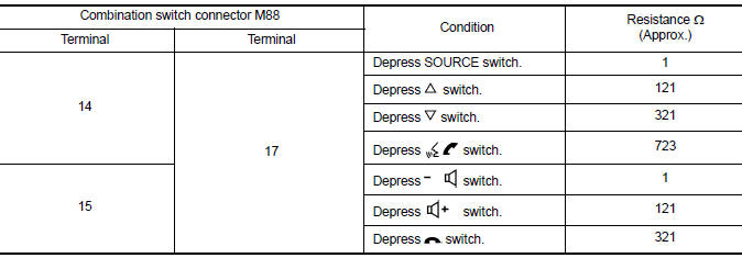
Is the inspection result normal?
YES >> GO TO 2.
NO >> Replace steering switches. Refer to AV "Removal and Installation".
2.CHECK COMBINATION SWITCH
Check continuity between combination switch connectors M88 and M30.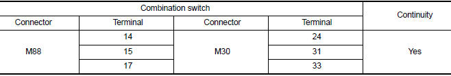
Is the inspection result normal?
YES >> GO TO 3.
NO >> Replace spiral cable. Refer to SR "Removal and Installation".
3.CHECK HARNESS BETWEEN COMBINATION SWITCH AND AV CONTROL UNIT
1. Disconnect AV control unit connector M30.
2. Check continuity between combination switch connector M30 and AV control
unit connector M70.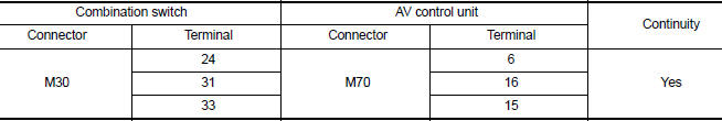
3. Check continuity between combination switch connector M30 and ground.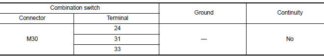
Is the inspection result normal?
YES >> Replace AV control unit. Refer to AV "Removal and Installation".
NO >> Repair or replace harness or connectors.
 Microphone signal circuit
Diagnosis Procedure Regarding Wiring Diagram information, refer to AV "Wiring Diagram". 1.CHECK MICROPHONE SIGNAL CIRCUIT CONTINUITY 1. Turn ignition switch OFF. 2. Disconnect AV control ...
USB Connector
Diagnosis Procedure Regarding Wiring Diagram information, refer to AV "Wiring Diagram". 1.CHECK USB INTERFACE HARNESS CONTINUITY 1. Turn ignition switch OFF. 2. Disconnect AV control uni ...
Other materials:
Refrigeration system
Refrigerant Cycle
REFRIGERANT FLOW
The refrigerant flows in the standard pattern, that is, through the
compressor, the condenser with liquid tank,
through the evaporator, and back to the compressor. The refrigerant evaporation
through the evaporator coils
are controlled by externally equaliz ...
Trunk open function
TRUNK OPEN FUNCTION : System Description
System Diagram
TRUNK LID OPENER OPERATION
When the BCM detects that trunk lid opener switch is pressed, it starts
the outside key antenna (rear
bumper) and inside key antenna and transmits the request signal to the
Intelligent Key. Then, c ...
Categories
- Manuals Home
- Nissan Versa Owners Manual
- Nissan Versa Service Manual
- Video Guides
- Questions & Answers
- External Resources
- Latest Updates
- Most Popular
- Sitemap
- Search the site
- Privacy Policy
- Contact Us

0.0049