Nissan Versa (N17): USB Connector
Diagnosis Procedure
Regarding Wiring Diagram information, refer to AV "Wiring Diagram".
1.CHECK USB INTERFACE HARNESS CONTINUITY
1. Turn ignition switch OFF.
2. Disconnect AV control unit connector M73 and USB interface connector M72.
3. Check continuity between AV control unit connector M73 and USB interface
connector M72.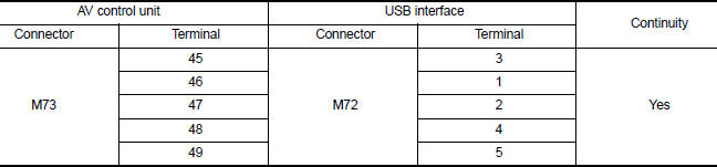
4. Check continuity between AV control unit connector M73 and ground.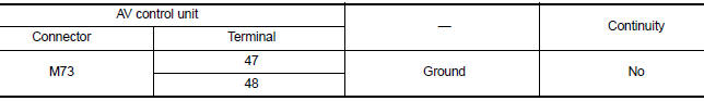
Is the inspection result normal?
YES >> Replace the USB interface. Refer to AV "Removal and Installation".
NO >> Repair or replace harness or connectors.
 Steering switch
Diagnosis Procedure Regarding Wiring Diagram information, refer to AV "Wiring Diagram". 1.CHECK STEERING WHEEL AUDIO CONTROL SWITCH RESISTANCE 1. Turn ignition switch OFF. 2. Disconnect ...
Auxiliary input jack
Diagnosis Procedure Regarding Wiring Diagram information, refer to AV "Wiring Diagram". 1.CHECK AUX JACK HARNESS CONTINUITY 1. Turn ignition switch OFF. 2. Disconnect AV control unit c ...
Other materials:
Drive belt idler pulley
Exploded View
1. Generator bracket 2. Center shaft 3. Spacer
4. Adjusting bolt 5. Washer 6. Idler pulley
7. Plate
Removal and Installation
REMOVAL
Remove the fender protector (RH).
Remove the air duct inlet assembly.
Remove drive belt.
Remove the lock nut, and then remove the pl ...
Line pressure control
LINE PRESSURE CONTROL : System Description
SYSTEM DIAGRAM
DESCRIPTION
Highly accurate line pressure control (secondary pressure control) reduces
friction for improvement of fuel
economy.
Normal Oil Pressure Control
Appropriate line pressure and secondary pressure suitable for driving
c ...
Categories
- Manuals Home
- Nissan Versa Owners Manual
- Nissan Versa Service Manual
- Video Guides
- Questions & Answers
- External Resources
- Latest Updates
- Most Popular
- Sitemap
- Search the site
- Privacy Policy
- Contact Us

0.0048