Nissan Versa (N17): STRG Branch line circuit
Diagnosis Procedure
1.CHECK CONNECTOR
1. Turn the ignition switch OFF.
2. Disconnect the battery cable from the negative terminal.
3. Check the terminals and connectors of the steering angle sensor for damage, bend and loose connection (unit side and connector side).
Is the inspection result normal?
YES >> GO TO 2.
NO >> Repair the terminal and connector.
2.CHECK HARNESS FOR OPEN CIRCUIT
1. Disconnect the connector of steering angle sensor.
2. Check the resistance between the steering angle sensor harness connector
terminals.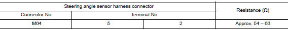
Is the measurement value within the specification?
YES >> GO TO 3.
NO >> Repair the steering angle sensor branch line.
3.CHECK POWER SUPPLY AND GROUND CIRCUIT
Check the power supply and the ground circuit of the steering angle sensor. Refer to BRC "Wiring Diagram".
Is the inspection result normal?
YES (Present error)>>Replace the steering angle sensor. Refer to BRC "Removal and Installation".
YES (Past error)>>Error was detected in the steering angle sensor branch line.
NO >> Repair the power supply and the ground circuit.
 M&A Branch line circuit
Diagnosis Procedure 1.CHECK CONNECTOR 1. Turn the ignition switch OFF. 2. Disconnect the battery cable from the negative terminal. 3. Check the terminals and connectors of the combination meter fo ...
BCM Branch line circuit
Diagnosis Procedure 1.CHECK CONNECTOR 1. Turn the ignition switch OFF. 2. Disconnect the battery cable from the negative terminal. 3. Check the terminals and connectors of the BCM for damage, bend ...
Other materials:
P0974 Shift solenoid A
DTC Logic
DTC DETECTION LOGIC
DTC
Trouble diagnosis name
DTC detection condition
Possible causes
P0974
Shift Solenoid "A" Control Circuit
High
The following diagnosis conditions
are met, and the TCM select
switch ON-OFF solenoid
valve monitor value is OF ...
Precautions
Precaution for Supplemental Restraint System
(SRS) "AIR BAG" and "SEAT BELT PRE-TENSIONER"
The Supplemental Restraint System such as "AIR BAG" and "SEAT BELT
PRE-TENSIONER", used along
with a front seat belt, helps to reduce the risk or severity of injury to the
driver and ...
Categories
- Manuals Home
- Nissan Versa Owners Manual
- Nissan Versa Service Manual
- Video Guides
- Questions & Answers
- External Resources
- Latest Updates
- Most Popular
- Sitemap
- Search the site
- Privacy Policy
- Contact Us

0.0049