Nissan Versa (N17): TCM Branch line circuit
Diagnosis Procedure
1.CHECK CONNECTOR
1. Turn the ignition switch OFF.
2. Disconnect the battery cable from the negative terminal.
3. Check the following terminals and connectors for damage, bend and loose connection (unit side and connector side).
- TCM
- Harness connector F8
- Harness connector E8
Is the inspection result normal?
YES >> GO TO 2.
NO >> Repair the terminal and connector.
2.CHECK HARNESS FOR OPEN CIRCUIT
1. Disconnect the connector of TCM.
2. Check the resistance between the TCM harness connector terminals.
- CVT models 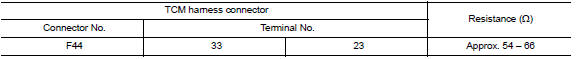
- A/T models 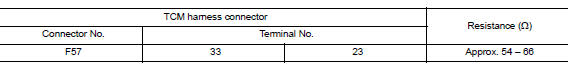
Is the measurement value within the specification?
YES >> GO TO 3.
NO >> Repair the TCM branch line.
3.CHECK POWER SUPPLY AND GROUND CIRCUIT
Check the power supply and the ground circuit of the TCM. Refer to the following.
- CVT models: TM "Diagnosis Procedure"
- A/T models: TM"Diagnosis Procedure"
Is the inspection result normal?
YES (Present error)>>Replace the TCM. Refer to the following.
- CVT models: TM "Removal and Installation"
- A/T models: TM "Removal and Installation"
YES (Past error)>>Error was detected in the TCM branch line.
NO >> Repair the power supply and the ground circuit.
 IPDM-E Branch line circuit
Diagnosis Procedure 1.CHECK CONNECTOR 1. Turn the ignition switch OFF. 2. Disconnect the battery cable from the negative terminal. 3. Check the terminals and connectors of the IPDM E/R for damag ...
A-BAG Branch line circuit
Diagnosis Procedure WARNING: Always observe the following items for preventing accidental activation. Before servicing, turn ignition switch OFF, disconnect battery negative terminal, and w ...
Other materials:
Cold weather driving
Freeing a frozen door lock
To prevent a door lock from freezing, apply deicer
through the key hole. If the lock becomes
frozen, heat the key before inserting it into the key
hole, or use the remote keyless entry key fob or
the NISSAN Intelligent Key.
Antifreeze
In the winter when it is antic ...
Additional service when replacing
ECM
Description
When replacing ECM, the following procedure must be performed.
PROGRAMMING OPERATION
NOTE:
After replacing with a blank ECM, programming is required to write ECM
information. Be sure to follow the procedure
to perform the programming.
Work Procedure
1.CHECK ECM PART NUMBER
Che ...
Categories
- Manuals Home
- Nissan Versa Owners Manual
- Nissan Versa Service Manual
- Video Guides
- Questions & Answers
- External Resources
- Latest Updates
- Most Popular
- Sitemap
- Search the site
- Privacy Policy
- Contact Us

0.0051