Nissan Versa (N17): IPDM-E Branch line circuit
Diagnosis Procedure
1.CHECK CONNECTOR
1. Turn the ignition switch OFF.
2. Disconnect the battery cable from the negative terminal.
3. Check the terminals and connectors of the IPDM E/R for damage, bend and loose connection (unit side and connector side).
Is the inspection result normal?
YES >> GO TO 2.
NO >> Repair the terminal and connector.
2.CHECK HARNESS FOR OPEN CIRCUIT
1. Disconnect the connector of IPDM E/R.
2. Check the resistance between the IPDM E/R harness connector terminals.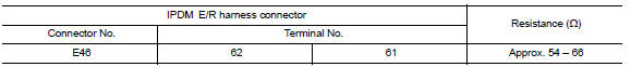
Is the measurement value within the specification?
YES >> GO TO 3.
NO >> Repair the IPDM E/R branch line.
3.CHECK POWER SUPPLY AND GROUND CIRCUIT
Check the power supply and the ground circuit of the IPDM E/R. Refer to the following.
- With Intelligent Key system: PCS "Diagnosis Procedure"
- Without Intelligent Key system: PCS"Diagnosis Procedure"
Is the inspection result normal?
YES (Present error)>>Replace the IPDM E/R. Refer to the following.
- With Intelligent Key system: PCS "Removal and Installation"
- Without Intelligent Key system: PCS "Removal and Installation"
YES (Past error)>>Error was detected in the IPDM E/R branch line.
NO >> Repair the power supply and the ground circuit.
 ABS Branch line circuit
Diagnosis Procedure 1.CHECK CONNECTOR 1. Turn the ignition switch OFF. 2. Disconnect the battery cable from the negative terminal. 3. Check the terminals and connectors of the ABS actuator and e ...
TCM Branch line circuit
Diagnosis Procedure 1.CHECK CONNECTOR 1. Turn the ignition switch OFF. 2. Disconnect the battery cable from the negative terminal. 3. Check the following terminals and connectors for damage, bend ...
Other materials:
Low tire pressure warning lamp
does not turn on
Diagnosis Procedure
NOTE:
The Signal Tech II Tool (J-50190) can be used to perform the following
functions. Refer to the Signal Tech II
User Guide for additional information.
Activate and display TPMS transmitter IDs
Display tire pressure reported by the TPMS transmitter
Read TPMS DTCs
...
Keyfob ID set up with consult
ID Code Entry Procedure
KEYFOB ID SET UP WITH CONSULT
NOTE:
If a keyfob is lost, the ID code of the lost keyfob must be erased
to prevent unauthorized use. A specific
ID code can be erased with CONSULT. However, when the ID code of a lost
keyfob is not known,
all controller ID code ...
Categories
- Manuals Home
- Nissan Versa Owners Manual
- Nissan Versa Service Manual
- Video Guides
- Questions & Answers
- External Resources
- Latest Updates
- Most Popular
- Sitemap
- Search the site
- Privacy Policy
- Contact Us

0.0046