Nissan Versa (N17): TCM Branch line circuit
Diagnosis Procedure
1.CHECK CONNECTOR
1. Turn the ignition switch OFF.
2. Disconnect the battery cable from the negative terminal.
3. Check the following terminals and connectors for damage, bend and loose connection (unit side and connector side).
- TCM
- Harness connector F8
- Harness connector E8
Is the inspection result normal?
YES >> GO TO 2.
NO >> Repair the terminal and connector.
2.CHECK HARNESS FOR OPEN CIRCUIT
1. Disconnect the connector of TCM.
2. Check the resistance between the TCM harness connector terminals.
- CVT models 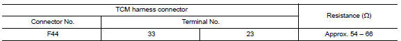
- A/T models 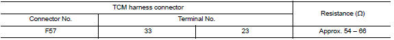
Is the measurement value within the specification?
YES >> GO TO 3.
NO >> Repair the TCM branch line.
3.CHECK POWER SUPPLY AND GROUND CIRCUIT
Check the power supply and the ground circuit of the TCM. Refer to the following.
- CVT models: TM "Diagnosis Procedure"
- A/T models: TM "Diagnosis Procedure"
Is the inspection result normal?
YES (Present error)>>Replace the TCM. Refer to the following.
- CVT models: TM "Removal and Installation"
- A/T models: TM "Removal and Installation"
YES (Past error)>>Error was detected in the TCM branch line.
NO >> Repair the power supply and the ground circuit.
 IPDM-E Branch line circuit
Diagnosis Procedure 1.CHECK CONNECTOR 1. Turn the ignition switch OFF. 2. Disconnect the battery cable from the negative terminal. 3. Check the terminals and connectors of the IPDM E/R for damage, ...
A-BAG Branch line circuit
Diagnosis Procedure WARNING: Always observe the following items for preventing accidental activation. Before servicing, turn ignition switch OFF, disconnect battery negative terminal, and wai ...
Other materials:
P0976 Shift solenoid B
DTC Logic
DTC DETECTION LOGIC
DTC
Trouble diagnosis name
DTC detection condition
Possible causes
P0976
Shift Solenoid B Control Circuit
Low
The following diagnosis conditions
are met, and the TCM low
clutch solenoid valve current
monitor reading is 200 m ...
Tire pressure monitoring system
TIRE PRESSURE MONITORING SYSTEM : System Diagram
TIRE PRESSURE MONITORING SYSTEM : System
Description
The BCM has pressure judgment and trouble diagnosis functions. When the
BCM detects low inflation pressure
or another unusual symptom, the low tire pressure warning lamp in the
c ...
Categories
- Manuals Home
- Nissan Versa Owners Manual
- Nissan Versa Service Manual
- Video Guides
- Questions & Answers
- External Resources
- Latest Updates
- Most Popular
- Sitemap
- Search the site
- Privacy Policy
- Contact Us

0.0048