Nissan Versa (N17): Parking brake switch signal circuit
Type A
TYPE A : Description
Transmits the parking brake switch signal to the combination meter.
TYPE A : Component Function Check
1.COMBINATION METER INPUT SIGNAL
1. Select "METER/M&A" on CONSULT.
2. Monitor "PKB SW" of "DATA MONITOR" while applying and releasing the parking brake.
PKB SW
Parking brake depressed : ON
Parking brake released : OFF
Is the inspection result normal?
YES >> Inspection End.
NO >> Refer to WCS "TYPE A : Diagnosis Procedure".
TYPE A : Diagnosis Procedure
Regarding Wiring Diagram information, refer to WCS "Wiring Diagram".
1.CHECK COMBINATION METER INPUT SIGNAL
1. Turn ignition switch ON.
2. Check the voltage between combination meter harness connector and ground.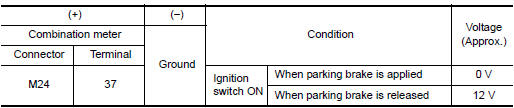
Is the inspection result normal?
YES >> Inspection End.
NO >> GO TO 2.
2.CHECK PARKING BRAKE SWITCH SIGNAL CIRCUIT
1. Turn ignition switch OFF.
2. Disconnect combination meter connector and parking brake switch connector.
3. Check continuity between combination meter harness connector and parking
brake switch harness connector.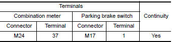
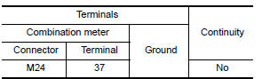
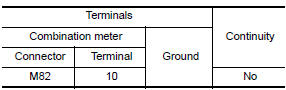
4. Check continuity between combination meter harness connector and ground.
Is the inspection result normal?
YES >> Inspection End.
NO >> Repair harness or connector.
TYPE A : Component Inspection
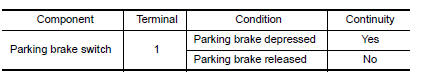
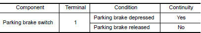
1.CHECK PARKING BRAKE SWITCH
Check continuity between parking brake switch terminal 1 and switch case
ground.
Is the inspection result normal?
YES >> Inspection End.
NO >> Replace parking brake switch.
Type B
TYPE B : Description
Transmits the parking brake switch signal to the combination meter.
TYPE B : Component Function Check
1.COMBINATION METER INPUT SIGNAL
1. Select "METER/M&A" on CONSULT.
2. Monitor "PKB SW" of "DATA MONITOR" while applying and releasing the parking brake.
PKB SW
Parking brake depressed : ON
Parking brake released : OFF
Is the inspection result normal?
YES >> Inspection End.
NO >> Refer to WCS "TYPE B : Diagnosis Procedure".
TYPE B : Diagnosis Procedure
Regarding Wiring Diagram information, refer to WCS "Wiring Diagram".
1.CHECK COMBINATION METER INPUT SIGNAL
1. Turn ignition switch ON.
2. Check the voltage between combination meter harness connector and ground.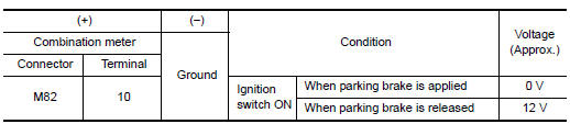
Is the inspection result normal?
YES >> Inspection End.
NO >> GO TO 2.
2.CHECK PARKING BRAKE SWITCH SIGNAL CIRCUIT
1. Turn ignition switch OFF.
2. Disconnect combination meter connector and parking brake switch connector.
3. Check continuity between combination meter harness connector and parking
brake switch harness connector.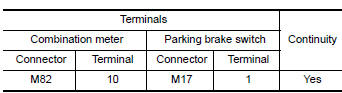
4. Check continuity between combination meter harness connector and ground.
Is the inspection result normal?
YES >> Inspection End.
NO >> Repair harness or connector.
TYPE B : Component Inspection
1.CHECK PARKING BRAKE SWITCH
Check continuity between parking brake switch terminal 1 and switch case
ground.
Is the inspection result normal?
YES >> Inspection End.
NO >> Replace parking brake switch.
SYMPTOM DIAGNOSIS
 Key switch signal circuit (without
intelligent key)
Key switch signal circuit (without
intelligent key)
Description Transmits a key switch signal to the BCM. Component Function Check 1. CHECK BCM INPUT SIGNAL Select "DATA MONITOR" for "BCM" and check the "KEY ON SW" monitor value. KEY ON SW ...
The parking brake release warning
continues sounding, or does not
sound
Description The parking brake warning buzzer sounds continuously during vehicle travel though the parking brake is released. The parking brake warning buzzer does not sound at all even thou ...
Other materials:
Additional service when replacing
ECM
Description
When replacing ECM, the following procedure must be performed.
PROGRAMMING OPERATION
NOTE:
After replacing with a blank ECM, programming is required to write ECM
information. Be sure to follow the procedure
to perform the programming.
Work Procedure
1.CHECK ECM PART NUMBER
Che ...
P072C Stuck in 1GR
DTC Logic
DTC DETECTION LOGIC
DTC
Trouble diagnosis name
DTC detection condition
Possible causes
P072C
Stuck in Gear 1
The following diagnosis conditions
are met and the detection
conditions continue for 0.5 seconds
or more.- Diagnosis condition
- Shifti ...
Categories
- Manuals Home
- Nissan Versa Owners Manual
- Nissan Versa Service Manual
- Video Guides
- Questions & Answers
- External Resources
- Latest Updates
- Most Popular
- Sitemap
- Search the site
- Privacy Policy
- Contact Us

0.0056