Nissan Versa (N17): Washer nozzle
Washer nozzle : Removal and Installation
REMOVAL
1. Remove cowl top cover. Refer to EXT "Removal and Installation".
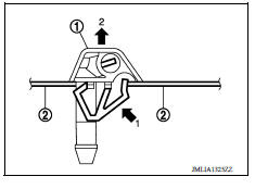
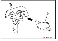
2. Disconnect washer tube from washer nozzle (1).
3. Place cowl top cover (2) up side down, then release washer nozzle pawl to remove as shown.
INSTALLATION
Installation is in the reverse order of removal.
CAUTION:
- The spray positions differ, check that left and right nozzles are installed correctly.
- Adjust the nozzle spray pattern. Refer to WW "WASHER NOZZLE : Inspection and Adjustment".
Washer nozzle : Inspection and Adjustment
INSPECTION
Check valve Inspection
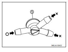
Check that air can pass through the nozzle by blowing into the nozzle and that air cannot flow in the opposite direction.
ADJUSTMENT
Washer Nozzle Spray Position Adjustment
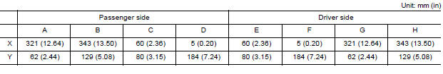
Adjust spray positions to match the positions shown.
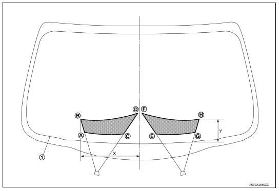
1. Black printed frame line
 : Spray area
1. If washer nozzle (1) spray pattern is not within specification adjust using suitable tool (A).
CAUTION: Do not use needle or small pin to adjust the washer nozzle.
NOTE:
- Washer nozzle adjuster is included with shipment of washer nozzle.
- If wax or dust gets into the nozzle, remove wax or dust with a needle or small pin.
 Washer pump
Exploded View 1. Washer tank 2. Front washer tube 3. Washer pump 4. Seal Front Removal and Installation REMOVAL 1. Remove fender protector. Refer to EXT "Removal and Installation" ...
Washer tube
WASHER TUBE : Removal and Installation REMOVAL 1. Remove front washer tube from the washer pump. Refer to WW "Removal and Installation". 2. Remove front washer tube from the front washe ...
Other materials:
Service data and specifications
(SDS)
Idle Speed
*: Under the following conditions
A/C switch: OFF
Electric load: OFF (Lights, heater fan & rear window defogger)
Steering wheel: Kept in straight-ahead position
Ignition Timing
*: Under the following conditions
A/C switch: OFF
Ele ...
A/T Fluid cooler
Cleaning
Whenever the A/T is repaired, overhauled, or replaced, the A/T fluid cooler
mounted in the radiator must be
inspected and cleaned.
Metal debris and friction material, if present, can become trapped in the A/T
fluid cooler. This debris can contaminate
the newly serviced A/T or, i ...
Categories
- Manuals Home
- Nissan Versa Owners Manual
- Nissan Versa Service Manual
- Video Guides
- Questions & Answers
- External Resources
- Latest Updates
- Most Popular
- Sitemap
- Search the site
- Privacy Policy
- Contact Us

0.0091