Nissan Versa (N17): Horn function
Description
Perform answer-back for each operation with horn.
Component Function Check
1.CHECK FUNCTION
- Select HORN in "ACTIVE TEST" mode with CONSULT.
- Check the horn operation.

Is the operation normal?
YES >> Inspection End.
NO >> Refer to DLK "Diagnosis Procedure".
Diagnosis Procedure
Regarding Wiring Diagram information, refer to DLK "Wiring Diagram".
1.CHECK HORN FUNCTION
Check horn function with horn switch.
Does the horn sound?
YES >> GO TO 2
NO >> Refer to HRN "Wiring Diagram".
2.CHECK HORN RELAY POWER SUPPLY
- Turn ignition switch ON.
- Perform "ACTIVE TEST" ("HORN") with CONSULT.
- Using an oscilloscope or analog voltmeter to check voltage between IPDM
E/R connector and ground.
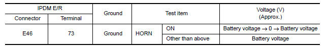
Is the inspection result normal?
YES >> Repair or replace open harness between IPDM E/R and horn relay.
NO >> GO TO 3
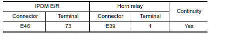
3.CHECK HORN RELAY CIRCUIT
- Turn ignition switch OFF.
- Disconnect IPDM E/R and horn relay connector.
- Check continuity between IPDM E/R harness connector and horn relay
harness connector.
- Check continuity between IPDM E/R harness connector and ground.
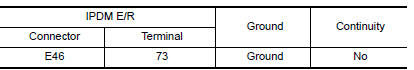
Is the inspection result normal?
YES >> GO TO 4
NO >> Repair or replace harness.
4.CHECK INTERMITTENT INCIDENT
Refer to GI "Intermittent Incident".
Is the inspection result normal?
YES >> Replace IPDM E/R. Refer to PCS "Removal and Installation".
NO >> Repair or replace the malfunctioning part.
 Keyfob battery and function
Description The following functions are available when having and carrying the keyfob. Door lock/unlock Panic mode (horn and headlamp operation) Remote control entry function and panic alarm ...
Warning chime function
Description Performs operation method guide and warning with buzzer. ...
Other materials:
Steering column covers
Removal and Installation
REMOVAL
Remove instrument lower panel LH. Refer to IP "Removal and
Installation".
Remove lower knee protector (LH) bolts and lower knee protector (LH).
Refer to IP "Exploded View".
Remove steering column covers.
a. Remove steering colu ...
Power supply and ground circuit
Diagnosis Procedure
Regarding Wiring Diagram information, refer to BCS "Wiring Diagram".
1.CHECK FUSES AND FUSIBLE LINK
Check that the following fuses and fusible link are not blown.
Is the fuse blown?
YES >> Replace the blown fuse or fusible link after repairing the affected ...
Categories
- Manuals Home
- Nissan Versa Owners Manual
- Nissan Versa Service Manual
- Video Guides
- Questions & Answers
- External Resources
- Latest Updates
- Most Popular
- Sitemap
- Search the site
- Privacy Policy
- Contact Us

0.0057