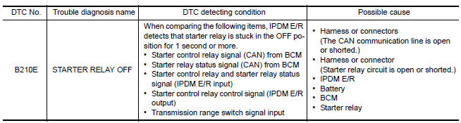
Nissan Versa (N17): B210E Starter relay
DTC Logic
DTC DETECTION LOGIC
NOTE:
- If DTC B210E is displayed with DTC U1000, first perform the trouble diagnosis for DTC U1000. Refer to BCS "DTC Logic".
- If DTC B210E is displayed with DTC B2605, first perform the trouble diagnosis for DTC B2605. Refer to BCS "DTC Logic".
- When IPDM E/R power supply voltage is low (Approx. 7 - 8 V for about
1 second), the DTC B210F may be
detected.
DTC CONFIRMATION PROCEDURE
1.PERFORM DTC CONFIRMATION PROCEDURE
1. Press push-button ignition switch under the following conditions to start engine, and wait 1 second or more.
Selector lever: In the P position
Brake pedal: Not depressed
2. Check DTC in Self Diagnostic Result mode of IPDM E/R using CONSULT.
Is DTC detected?
YES >> Go to SEC "Diagnosis Procedure".
NO >> Inspection End.
Diagnosis Procedure
Regarding Wiring Diagram information, refer to SEC "Wiring Diagram".
1.CHECK STARTER RELAY OUTPUT SIGNAL
1. Check voltage between BCM harness connector and ground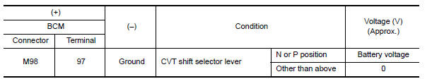
Is the inspection result normal?
YES >> GO TO 4.
NO >> GO TO 2.
2.CHECK STARTER RELAY OUTPUT SIGNAL CIRCUIT
1. Turn ignition switch OFF.
2. Disconnect BCM connector.
3. Disconnect starter relay.
4. Check continuity between BCM harness connector and starter relay harness
connector. 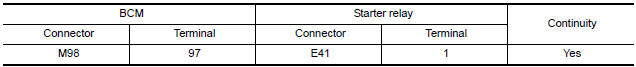
5. Check continuity between BCM harness connector and ground. 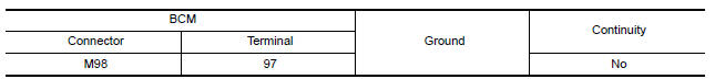
Is the inspection result normal?
YES >> GO TO 3.
NO >> Repair or replace harness.
3.CHECK STARTER RELAY CIRCUIT 1
1. Turn ignition switch OFF.
2. Disconnect IPDM E/R connector.
3. Check continuity between IPDM E/R harness connector and starter relay
harness connector. 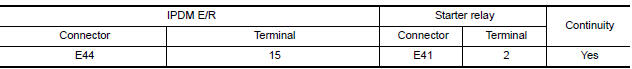
4. Check continuity between BCM harness connector and ground.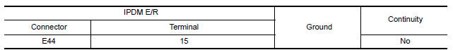
Is the inspection result normal?
YES >> GO TO 6.
NO >> Repair or replace harness.
4.CHECK STARTER RELAY POWER SUPPLY CIRCUIT
1. Turn ignition switch OFF.
2. Disconnect starter relay.
3. Check voltage between starter relay harness connector and ground.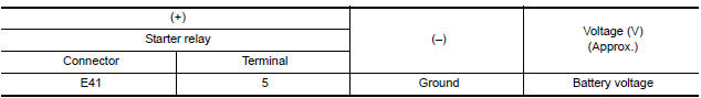
Is the inspection result normal?
YES >> GO TO 5.
NO-1 >> Check 40 A fusible link [Figure H, located in the fuse block (J/B)].
NO-2 >> Check harness for open or short between starter relay and fusible link.
5.CHECK STARTER RELAY CIRCUIT 2
1. Disconnect IPDM E/R connector.
2. Check continuity between IPDM E/R harness connector and starter relay
harness connector.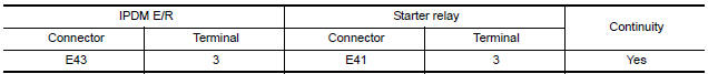
3. Check continuity between BCM harness connector and ground.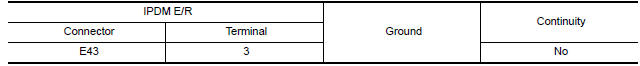
Is the inspection result normal?
YES >> GO TO 6.
NO >> Repair or replace harness.
6.CHECK STARTER RELAY
Refer to SEC "Component Inspection".
Is the inspection result normal?
YES >> GO TO 7.
NO >> Replace starter relay.
7.REPLACE BCM
1. Replace BCM. Refer to BCS "Removal and Installation".
2. Perform initialization of BCM and registration of all Intelligent keys using CONSULT.
3. Perform DTC CONFIRMATION PROCEDURE for DTC B210E. Refer to SEC "DTC Logic".
Is the inspection result normal?
YES >> Inspection End.
NO >> Replace IPDM E/R. Refer to PCS "Removal and Installation".
Component Inspection
1.CHECK STARTER RELAY
1. Turn ignition switch OFF.
2. Disconnect starter relay.
3. Check continuity between starter relay terminals. 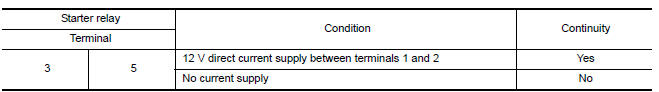
Is the inspection result normal?
YES >> Inspection End.
NO >> Replace starter relay.
 B210D Starter relay
Other materials:
Maintenance precautions
When performing any inspection or maintenance
work on your vehicle, always take care to prevent
serious accidental injury to yourself or damage to
the vehicle. The following are general precautions
which should be closely observed.
WARNING
Park the vehicle on a level surface, apply
the pa ...
Air cleaner and air duct
Exploded View
1. Clamp 2. PCV hose 3. Clamp
4. Mount rubber 5. Air duct (inlet) 6. Air cleaner body
7. Grommet 8. Air cleaner filter 9. Air cleaner cover
10. Mass air flow sensor 11. Air duct 12. Clamp
Removal and Installation
REMOVAL
NOTE:
Mass air flow sensor is removable as an assemb ...
Categories
- Manuals Home
- Nissan Versa Owners Manual
- Nissan Versa Service Manual
- Video Guides
- Questions & Answers
- External Resources
- Latest Updates
- Most Popular
- Sitemap
- Search the site
- Privacy Policy
- Contact Us

0.0054