Nissan Versa (N17): Diagnosis system (TCM)
DIAGNOSIS DESCRIPTION
Diagnosis description : 1 Trip detection diagnosis and 2 Trip detection diagnosis
NOTE: "Start the engine and turn OFF the ignition switch after warm-up." This is defined as 1 trip.
1 TRIP DETECTION DIAGNOSIS
When initial malfunction is detected, TCM memorizes DTC. In these diagnoses, some illuminate MIL and some do not. Refer to TM "DTC Index".
2 TRIP DETECTION DIAGNOSIS
When initial malfunction is detected, TCM memorizes DTC of the 1st trip. MIL does not light at this stage. <1 trip> If the same malfunction is detected again in next driving, TCM memorizes DTC. When DTC is memorized, MIL lights. <2 trip> "Trip" of the "2 trip detection diagnosis" indicates the driving mode that executes self-diagnosis during driving.
| Item | DTC at the 1st trip | DTC | MIL | |||
| Display at the 1st trip | Display at the 2nd trip | Display at the 1st trip | Display at the 2nd trip | Illumination at the 1st trip | Illumination at the 2nd trip | |
| 1 trip detection diagnosis (Refer to TM "DTC Index") | - | - | × | - | × | - |
| 2 trip detection diagnosis (Refer to TM "DTC Index") | × | - | - | × | - | × |
Diagnosis description : DTC and DTC of 1st Trip
2 TRIP DETECTION DIAGNOSIS THAT ILLUMINATES MIL
- The DTC number of the 1st trip is the same as the DTC number.
- When a malfunction is detected at the 1st trip, TCM memorizes DTC of the 1st trip. MIL does not light at this stage. If the same malfunction is not detected at the 2nd trip (conforming to necessary driving conditions), DTC at the 1st trip is erased from TCM. If the same malfunction is detected at the 2nd trip, TCM memorizes DTC and MIL lights at the same time.
- The DTC of the 1st trip is specified in Service $01 of SAE J1979/ISO 15031-5. Since detection of DTC at the 1st trip does not illuminate MIL, warning for a problem is not given to a driver.
- For procedure to delete DTC and 1st trip DTC from TCM, refer to TM "CONSULT Function".
- If DTC of the 1st trip is detected, it is necessary to check the cause according to the "Diagnosis flow". Refer to TM "Work Flow".
DIAGNOSIS DESCRIPTION : Malfunction Indicator Lamp (MIL)
- TCM not only detects DTC, but also sends the MIL signal to ECM through CAN communication. ECM sends the MIL signal to the combination meter through CAN communication according to the signal, and illuminates MIL.
- For malfunction indicator lamp (MIL) description, refer to EC "DIAGNOSIS DESCRIPTION : Malfunction Indicator Lamp (MIL)".
Diagnosis description : counter system
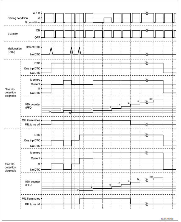
RELATION BETWEEN DTC AT 1ST TRIP/DTC/MIL AND DRIVING CONDITIONS (FOR 2 TRIP DETECTION DIAGNOSIS THAT ILLUMINATES MIL)
- When initial malfunction is detected, TCM memorizes DTC of the 1st trip. MIL does not light at this stage.
- If the same malfunction is detected at the 2nd trip, TCM memorizes DTC and MIL lights at the same time.
- Then, MIL goes after driving the vehicle for 3 trips under "Driving condition B" without malfunction.
- DTC is displayed until 40 trips of "Driving condition A" are satisfied
without detecting the same malfunction.
DTC is erased when 40 trips are satisfied.
- .When the self-diagnosis result is acceptable at the 2nd trip (conforming to driving condition B), DTC of the 1st trip is erased.
COUNTER SYSTEM LIST 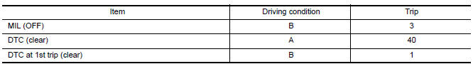
DRIVING CONDITION
Driving condition A
Driving condition A is the driving condition that provides warm-up.
In specific, count-up is performed when all of the following conditions are satisfied.
- Engine speed is 400 rpm or more.
- After start of the engine, the water temperature increased by 20 C (36 F) or more.
- Water temperature was 70 C (158 F) or more.
- The ignition switch was changed from ON to OFF.
NOTE:
- If the same malfunction is detected regardless of the driving condition, reset the A counter.
- When the above is satisfied without detecting the same malfunction, count up the A counter.
- When MIL goes off due to the malfunction and the A counter reaches 40, the DTC is erased.
Driving condition B
Driving condition B is the driving condition that performs all diagnoses once.
In specific, count-up is performed when all of the following conditions are satisfied.
- Engine speed is 400 rpm or more.
- Water temperature was 70 C (158 F) or more.
- In closed loop control, vehicle speed of 70 - 120 km/h (43 - 75 MPH) continued for 60 seconds or more.
- In closed loop control, vehicle speed of 30 - 60 km/h (19 - 37 MPH) continued for 10 seconds or more.
- In closed loop control, vehicle speed of 4 km/h (2 MPH) or less and idle determination ON continued for 12 seconds or more.
- After start of the engine, 22 minutes or more have passed.
- The condition that the vehicle speed is 10km/h (6 MPH) or more continued for 10 seconds or more in total.
- The ignition switch was changed from ON to OFF.
NOTE:
- If the same malfunction is detected regardless of the driving condition, reset the B counter.
- When the above is satisfied without detecting the same malfunction, count up the B counter.
- When the B counter reaches 3 without malfunction, MIL goes off.
- When the B counter is counted once without detecting the same malfunction after TCM memorizes DTC of the 1st trip, DTC of the 1st trip is erased.
TIME CHART
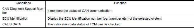
Consult function
APPLICATION ITEMS 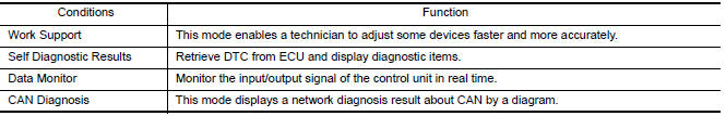
SELF DIAGNOSTIC RESULTS
Refer to TM "DTC Index".
DTC at 1st trip and method to read DTC
- DTC (P0705, P0711, P0720, etc.) is specified by SAE J2012/ISO 15031-6.
- DTC and DTC at 1st trip are displayed on "Self Diagnostic results" of
CONSULT.
When DTC is currently detected, "CRNT" is displayed. If "PAST" is displayed, it shows a malfunction occurred in the past.The trip number of drive without malfunction of concerned DTC can be confirmed with "IGN counter" inside "FFD".
- When the DTC at the 1st trip is detected, the "timing" is displayed as "1t".
DTC deletion method
NOTE:
- If the battery terminal is disconnected, the TCM memory is erased. (The disconnection time varies from several seconds to several hours.
- If the ignition switch is left ON after repair, turn OFF the ignition
switch and wait for 10 seconds or more.
Then, turn the ignition ON again. (Engine stop)
- Touch "TRANSMISSION" of CONSULT.
- Touch "Self Diagnostic Result".
- Touch "Erase". (DTC memorized in TCM is erased.)
IGN counter
The ignition counter is displayed in "FFD" and the number of times of satisfied "Driving condition A" is displayed after normal recovery of DTC. Refer to EC "DIAGNOSIS DESCRIPTION : Counter System".
- If malfunction (DTC) is currently detected, "0" is displayed.
- After normal recovery, every time "Driving condition A" is satisfied, the display value increases from 1 → 2 → 3...38 → 39.
- When MIL turns OFF due to the malfunction and the counter reaches 40, the DTC is erased.
NOTE: The counter display of "40" cannot be checked.
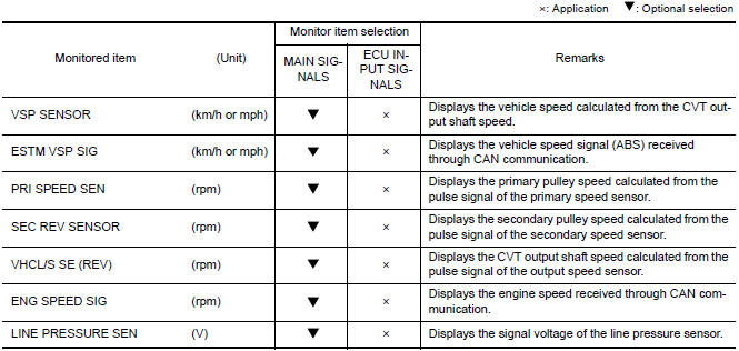
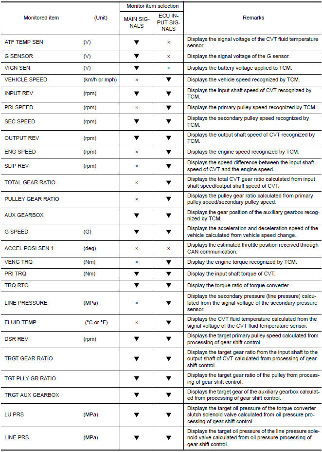
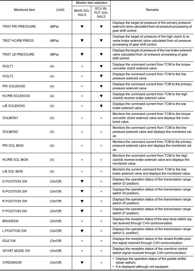
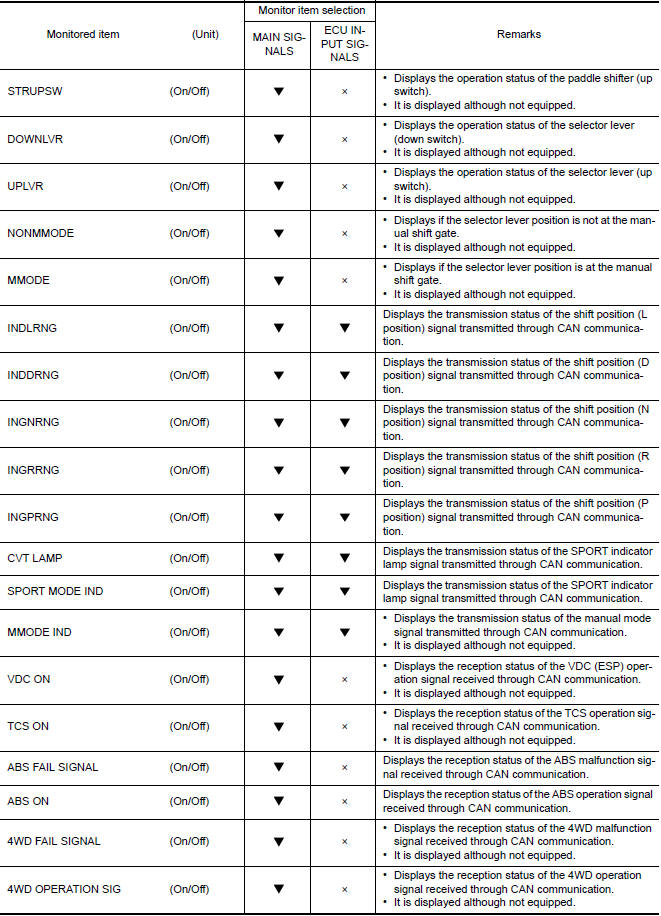
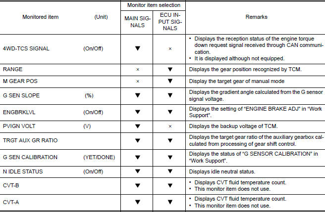
DATA MONITOR
NOTE: The following table includes information (items) inapplicable to this vehicle. For information (items) applicable to this vehicle, refer to CONSULT display items.
WORK SUPPORT
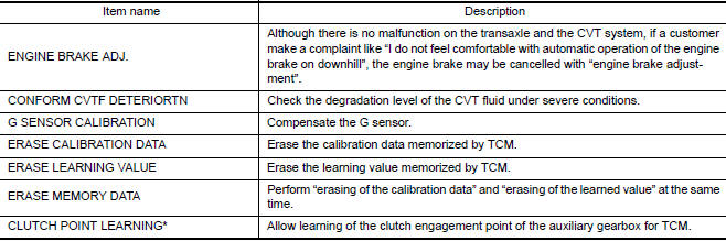
*: "Clutch point learning" can be selected, but do not use it.Engine brake adjustment
Engine brake adjustment
ENGINE BRAKE LEVEL
ON : Turn ON the engine brake control.
OFF : Turn OFF the engine brake control.
Check the degradation level of the CVT fluid.
CVTF degradation level data
210,000 or more : Replacement of the CVT fluid is required.
Less than 210,000 : Replacement of the CVT fluid is not required.
ECU DIAGNOSIS INFORMATION
 Idle neutral control
IDLE NEUTRAL CONTROL : System Description SYSTEM DIAGRAM DESCRIPTION If a driver has no intention of starting the vehicle in D position, TCM operates the low brake solenoid valve and control ...

Other materials:
Low tire pressure warning lamp
does not turn on
Diagnosis Procedure
NOTE:
The Signal Tech II Tool (J-50190) can be used to perform the following
functions. Refer to the Signal Tech II
User Guide for additional information.
Activate and display TPMS transmitter IDs
Display tire pressure reported by the TPMS transmitter
Read TPMS DTCs
...
Door mirror assembly
DOOR MIRROR ASSEMBLY : Removal and Installation
REMOVAL
CAUTION:
Use the following steps to disengage the door mirror corner cover from the
mirror assembly. Other
methods to remove the door mirror corner cover may damage the pawls.
1. Remove door mirror corner cover.
a. Fully open door wi ...
Categories
- Manuals Home
- Nissan Versa Owners Manual
- Nissan Versa Service Manual
- Video Guides
- Questions & Answers
- External Resources
- Latest Updates
- Most Popular
- Sitemap
- Search the site
- Privacy Policy
- Contact Us

0.0058