Nissan Versa (N17): B1017, B1018, B1020, B1021, B1022, B1025, B1032, B1048 OCS System
Description
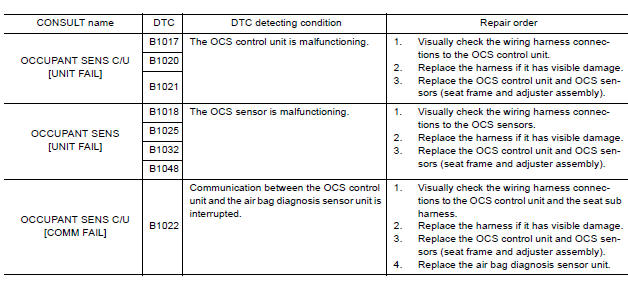
DTC B1017, B1018, B1020, B1021, B1022, B1025, B1032, B1048 OCCUPANT CLASSIFICATION SYSTEM (OCS)
The OCS control unit is wired to the air bag diagnosis sensor unit. The air bag diagnosis sensor unit will monitor the OCS for failures and interruptions in communication between the OCS control unit and the air bag diagnosis sensor unit.
PART LOCATION
Refer to SRC "Component Parts Location".
DTC Logic
DTC DETECTION LOGIC
With CONSULT
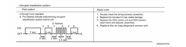
Without CONSULT
DTC CONFIRMATION PROCEDURE (With CONSULT)
1.CHECK SELF-DIAG RESULT
- Turn ignition switch ON.
- Check for DTC using CONSULT.
Is the DTC detected?
YES (Current DTC)>>Refer to SRC "Diagnosis Procedure".
YES (Past DTC)>>GO TO 2.
NO >> Inspection End.
2.ERASE SELF-DIAG RESULT
Erase the DTC using CONSULT.
Can the DTC be erased?
YES >> Inspection End.
NO >> Refer to SRC "Diagnosis Procedure".
DTC CONFIRMATION PROCEDURE (Without CONSULT)
1.CHECK SELF-DIAG RESULT
- Turn ignition switch ON.
- Check the air bag warning lamp status. Refer to SRC "Trouble Diagnosis without CONSULT".
NOTE: SRS will not enter diagnosis mode if no malfunction is detected in user mode.
Is the DTC detected?
YES >> Refer to SRC "Diagnosis Procedure".
NO >> Inspection End.
Diagnosis Procedure
1.HARNESS CONNECTOR
Visually inspect all applicable harness connectors for the following:
- Visible damage to connector or terminal
- Loose terminal
- Poor connection
NOTE: All harness connectors should be inspected from the air bag diagnosis unit to the end component (including any in-line connectors).
Is the inspection result normal?
YES >> GO TO 2.
NO >> Perform one of the following repairs:
- Visible damage: Replace the harness.
- Loose terminal: Secure the terminal.
- Poor connection: Secure the connection.
2.CONFIRM DTC
- Reconnect all harness connectors.
- Turn ignition switch ON.
- Check for DTC using CONSULT.
Is DTC still current?
YES >> GO TO 3
NO >> Refer to GI5 "Intermittent Incident".
3.WIRING HARNESS
Check the wiring harness for visible damage NOTE.
NOTE: The entire wiring harness should be inspected from the air bag diagnosis sensor unit to the end component (including any in-line connectors).
Is the inspection result normal?
YES >> GO TO 4.
NO >> Replace the harness.
4.CONFIRM DTC
- Reconnect all harness connectors.
- Turn ignition switch ON.
- Check for DTC using CONSULT.
Is DTC still current?
YES >> GO TO 5.
NO >> Refer toGI "Intermittent Incident".
5.AIR BAG DIAGNOSIS SENSOR UNIT
- Replace the air bag diagnosis sensor unit. Refer to SR "Removal and Installation".
- Turn ignition switch ON.
- Check for DTC using CONSULT.
Is DTC still current?
YES >> GO TO 6.
NO >> Clear DTC. Inspection End.
6.REPLACE OCS CONTROL UNIT AND SENSORS
Replace the OCS control unit and OCS sensors (seat frame and adjuster assembly). Refer to SR "Removal and Installation".
>> END
 B1023 Passenger air bag off indicator
Description DTC B1023 FRONT PASSENGER AIR BAG OFF INDICATOR The front passenger air bag off indicator is wired to the air bag diagnosis sensor unit. The air bag diagnosis sensor unit monitors the ...
B1209 - B1210 Collision detection
Description DTC B1209 - B1210 COLLISION DETECTION The air bag diagnosis sensor unit will set this DTC if it has detected a collision which has resulted in a frontal or side deployment of one or m ...
Other materials:
Power supply and ground circuit
Diagnosis Procedure
1.CHECK GROUND CONNECTION
Turn ignition switch OFF.
Check ground connection E. Refer to Ground Inspection in GI, "Circuit
Inspection".
Is the inspection result normal?
YES >> GO TO 2.
NO >> Repair or replace ground connection.
2.CHECK ECM G ...
Main power supply and ground circuit
Diagnosis Procedure
1.CHECK TCM POWER CIRCUIT (PART 1)
Turn ignition switch OFF.
Disconnect TCM connector.
Check voltage between TCM harness connector terminals and ground.
Is the inspection result normal?
YES >> GO TO 2.
NO >> G ...
Categories
- Manuals Home
- Nissan Versa Owners Manual
- Nissan Versa Service Manual
- Video Guides
- Questions & Answers
- External Resources
- Latest Updates
- Most Popular
- Sitemap
- Search the site
- Privacy Policy
- Contact Us

0.0078