Nissan Versa (N17): B2627 Outside antenna
DTC Logic
DTC DETECTION LOGIC 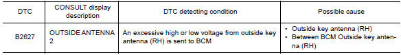
DTC CONFIRMATION PROCEDURE
1.PERFORM DTC CONFIRMATION PROCEDURE
- Turn ignition switch ON.
- Check Self Diagnostic Result mode of BCM using CONSULT.
Is outside key antenna DTC detected?
YES >> Refer to DLK "Diagnosis Procedure".
NO >> Outside key antenna (RH) is OK.
Diagnosis Procedure
Regarding Wiring Diagram information, refer to DLK"INTELLIGENT KEY SYSTEM : Wiring Diagram".
1.CHECK OUTSIDE KEY ANTENNA INPUT SIGNAL 1
- Turn ignition switch ON.
- Check signal between BCM harness connector and ground using
oscilloscope.
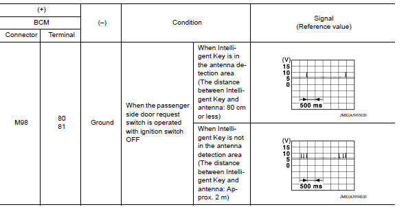
Is the inspection result normal?
YES >> Replace BCM. Refer to BCS "Removal and Installation".
NO >> GO TO 2.
2.CHECK OUTSIDE KEY ANTENNA CIRCUIT
- Turn ignition switch OFF.
- Disconnect BCM connector and outside key antenna (RH) connector.
- Check continuity between BCM harness connector and outside key antenna (RH)
harness connector.

- Check continuity between BCM harness connector and ground.
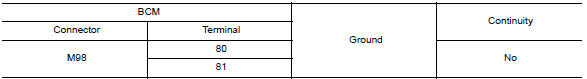
Is the inspection result normal?
YES >> GO TO 3.
NO >> Repair or replace harness.
3.CHECK OUTSIDE KEY ANTENNA INPUT SIGNAL 2
- Replace outside key antenna (RH). (New antenna or other antenna)
- Connect BCM connector and outside key antenna (RH) connector.
- Turn ignition switch ON.
- Check signal between BCM harness connector and ground using
oscilloscope.
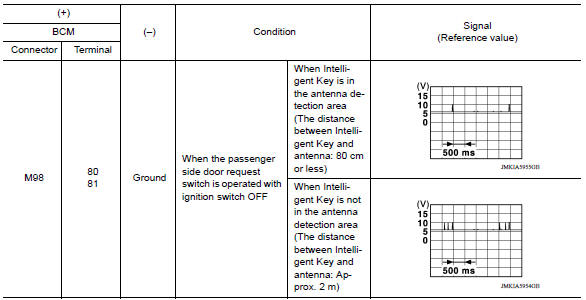
Is the inspection result normal?
YES >> Replace outside key antenna (RH).
NO >> Replace BCM. Refer to BCS "Removal and Installation".
 B2626 Outside antenna
Other materials:
Windshield-washer fluid
Windshield-washer fluid reservoir
Add a washer solvent to the windshield-washer
fluid reservoir for better cleaning. In the winter
season, add a windshield-washer antifreeze. Follow
the manufacturer's instructions for the mixture
ratio.
Refill the reservoir more frequently when driving
...
Thermostat
Exploded View
1. Radiator hose (lower) 2. Water inlet 3. Rubber ring
4. Thermostat A. To radiator
Removal and Installation
WARNING:
Do not remove the radiator cap when the engine is hot. Serious burns
could occur from highpressure
engine coolant escaping from the radiator. Wrap a thick cl ...
Categories
- Manuals Home
- Nissan Versa Owners Manual
- Nissan Versa Service Manual
- Video Guides
- Questions & Answers
- External Resources
- Latest Updates
- Most Popular
- Sitemap
- Search the site
- Privacy Policy
- Contact Us

0.0063