Nissan Versa (N17): B2196 Dongle unit
Description
BCM performs ID verification between BCM and dongle unit.
When verification result is OK, BCM permits cranking.
DTC Logic
DTC DETECTION LOGIC 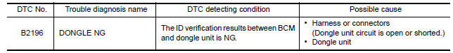
DTC CONFIRMATION PROCEDURE
1.PERFORM DTC CONFIRMATION PROCEDURE
1. Turn ignition switch ON.
2. Turn ignition switch OFF.
3. Turn ignition switch ON.
4. Check DTC in "Self-diagnosis result" mode of "BCM" using CONSULT.
Is the DTC detected?
YES >> Refer to SEC "Diagnosis Procedure".
NO >> Inspection End.
Diagnosis Procedure
Regarding Wiring Diagram information, refer to SEC "Wiring Diagram".
1.PERFORM INITIALIZATION
1. Perform initialization of BCM and registration of all mechanical keys using CONSULT.
For initialization and registration procedures, refer to CONSULT Immobilizer mode and follow the onscreen instructions.
2. Start the engine.
Dose the engine start?
YES >> Inspection End.
NO >> GO TO 2.
2.CHECK DONGLE UNIT CIRCUIT
1. Turn ignition switch OFF.
2. Disconnect BCM connector and dongle unit connector.
3. Check continuity between BCM harness connector and dongle unit harness
connector. 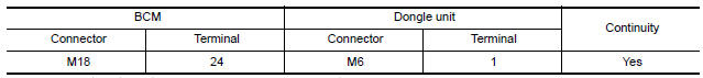
4. Check continuity between BCM harness connector and ground.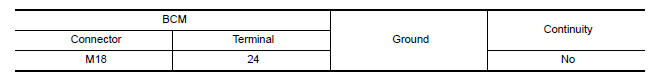
Is the inspection result normal?
YES >> GO TO 3.
NO >> Repair or replace harness.
3.CHECK DONGLE UNIT GROUND CIRCUIT
Check continuity between dongle unit harness connector and ground. 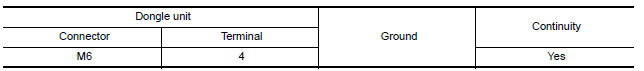
Is the inspection result normal?
YES >> Replace dongle unit.
NO >> Repair or replace harness.
 B2195 Anti-scanning
Power supply and ground circuit
Diagnosis Procedure Regarding Wiring Diagram information, refer to BCS "Wiring Diagram". 1.CHECK FUSES AND FUSIBLE LINK Check that the following fuses and fusible link are not blown. ...
Other materials:
Windshield-washer fluid
Windshield-washer fluid reservoir
Add a washer solvent to the windshield-washer
fluid reservoir for better cleaning. In the winter
season, add a windshield-washer antifreeze. Follow
the manufacturer's instructions for the mixture
ratio.
Refill the reservoir more frequently when driving
...
P0979 Shift solenoid C
DTC Logic
DTC DETECTION LOGIC
DTC
Trouble diagnosis name
DTC detection condition
Possible causes
P0979
Shift Solenoid C Control Circuit
Low
The following diagnosis conditions
are met, and the current
monitor reading of the TCM 2-4
brake solenoid valve is ...
Categories
- Manuals Home
- Nissan Versa Owners Manual
- Nissan Versa Service Manual
- Video Guides
- Questions & Answers
- External Resources
- Latest Updates
- Most Popular
- Sitemap
- Search the site
- Privacy Policy
- Contact Us

0.0057