Nissan Versa (N17): IPDM E/R (Intelligent power distribution module engine room)
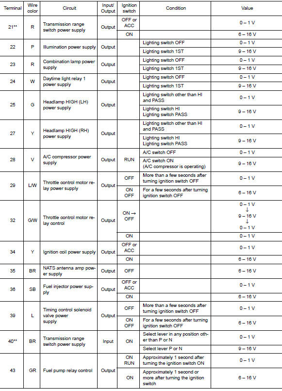
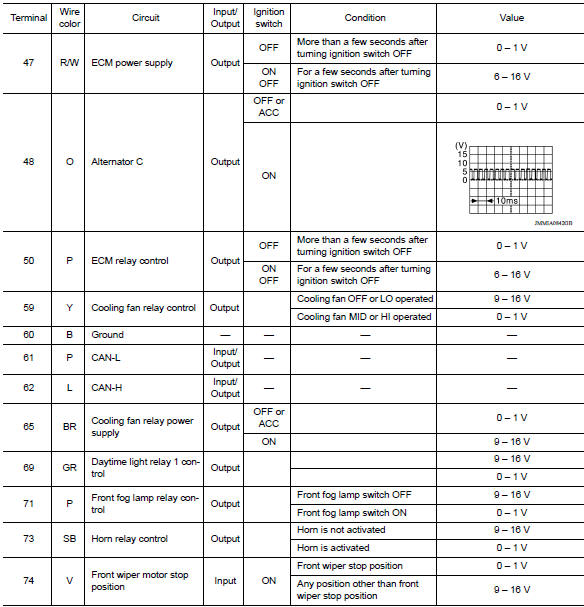
Reference Value
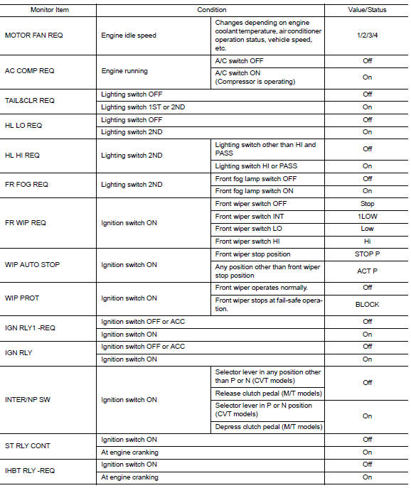
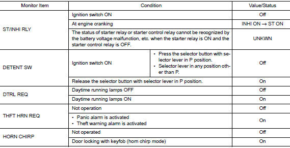
VALUES ON THE DIAGNOSIS TOOL
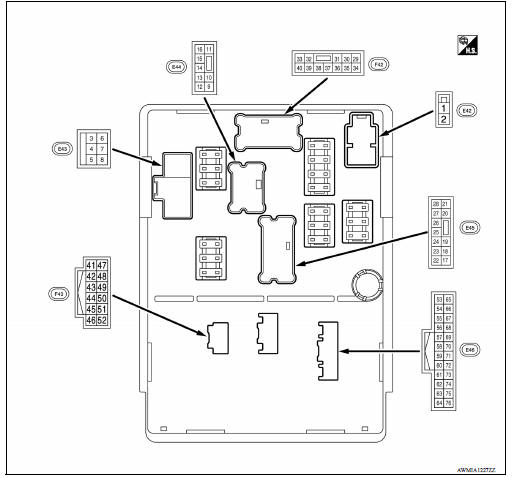
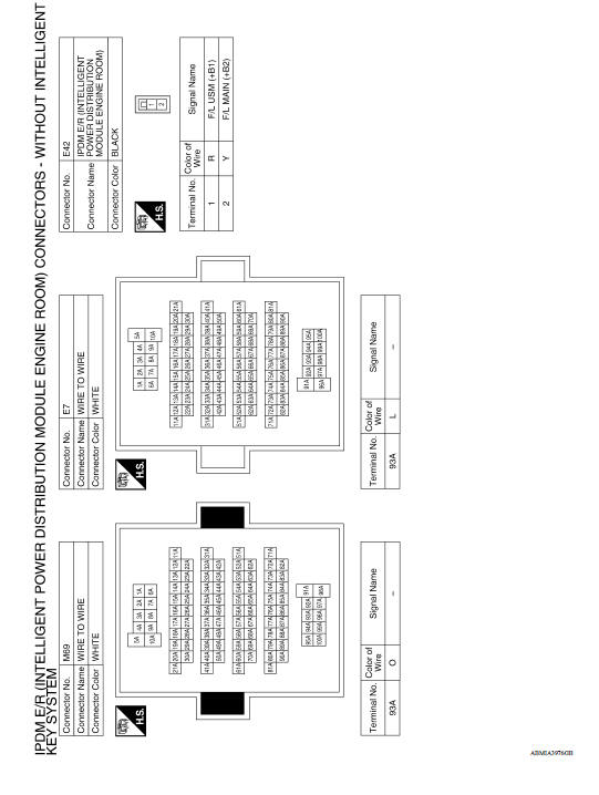
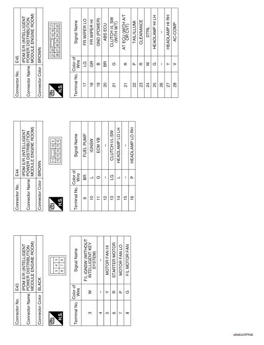
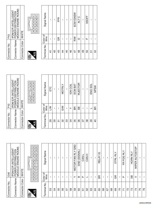
TERMINAL LAYOUT
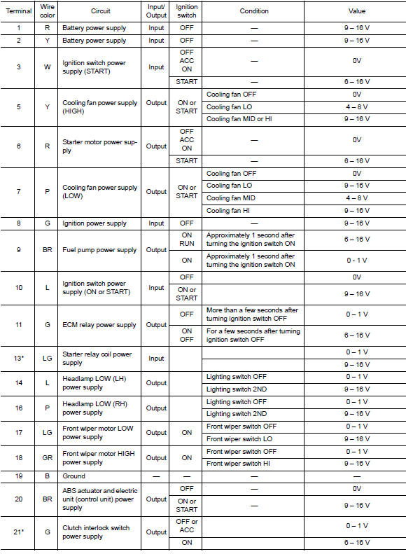
PHYSICAL VALUES
*:M/T
**:CVT or A/T
Fail-Safe
CAN COMMUNICATION CONTROL
When CAN communication with ECM and BCM is impossible, IPDM E/R performs fail-safe control. After CAN communication recovers normally, it also returns to normal control.
If No CAN Communication Is Available With ECM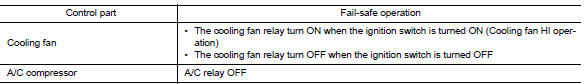
If No CAN Communication Is Available With BCM 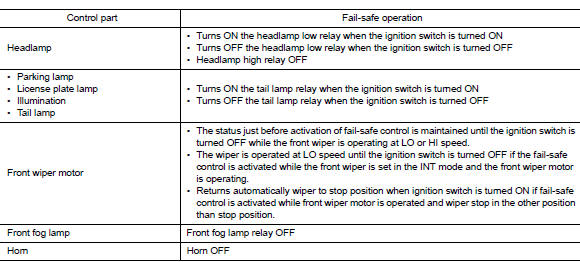
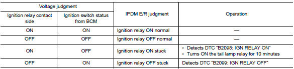
IGNITION RELAY MALFUNCTION DETECTION FUNCTION
- IPDM E/R monitors the voltage at the contact circuit of the ignition relay inside and ignition switch status from BCM via CAN communication.
- IPDM E/R judges the ignition relay error if the voltage differs between the contact circuit and the ignition switch status from BCM via CAN communication.
- If the ignition relay cannot turn OFF due to contact seizure, it
activates the tail lamp relay for 10 minutes to
alert the user to the ignition relay malfunction when the ignition switch is
turned OFF.
FRONT WIPER PROTECTION FUNCTION
IPDM E/R detects front wiper stop position by a front wiper stop position signal.
When a front wiper stop position signal is in the conditions listed below,
IPDM E/R stops power supply to wiper
after repeating a front wiper 10 seconds activation and 20 seconds stop.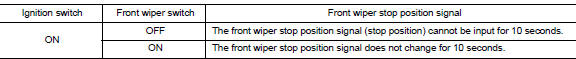
NOTE: This operation status can be confirmed on the IPDM E/R "Data Monitor" that displays "BLOCK" for the item "WIP PROT" while the wiper is stopped.
DTC Index
NOTE:
- The details of time display are as follows.
- CRNT: A malfunction is detected now.
- PAST: A malfunction was detected in the past.
- IGN counter is displayed on FFD (Freeze Frame data).
- The number is 0 when is detected now.
- The number increases like 1 → 2 * * * 38 → 39 after returning to the normal condition whenever IGN OFF → ON.
The number is fixed to 39 until the self-diagnosis results are erased if it
is over 39.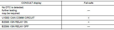
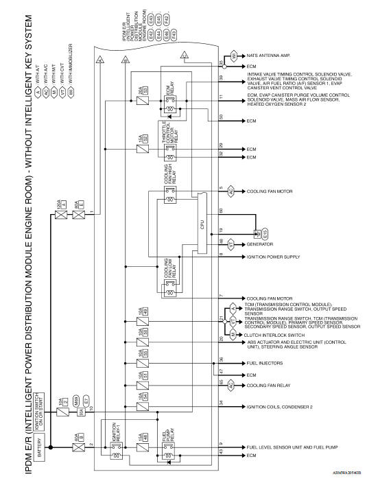
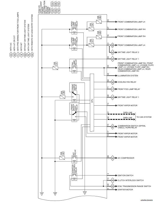
WIRING DIAGRAM
IPDM E/R (INTELLIGENT POWER DISTRIBUTION MODULE ENGINE ROOM)
Wiring Diagram
DTC/CIRCUIT DIAGNOSIS
 Diagnosis system (IPDM E/R)
Diagnosis Description AUTO ACTIVE TEST Description In auto active test, the IPDM E/R sends a drive signal to the following systems to check their operation. Front wiper (LO, HI) Parking l ...
U1000 CAN Comm circuit
Description Refer to LAN "CAN COMMUNICATION SYSTEM : System Description". DTC Logic DTC DETECTION LOGIC Diagnosis Procedure 1. PERFORM SELF DIAGNOSTIC RESULT 1. Turn ignition swi ...
Other materials:
Security systems (if so equipped)
Your vehicle has one type of security systems:
NISSAN Vehicle Immobilizer System
NISSAN vehicle immobilizer system
The NISSAN Vehicle Immobilizer System will not
allow the engine to start without the use of a
registered key.
If the engine fails to start using a registered key
(for ex ...
Transverse link
Exploded View
1. Front suspension member 2. Transverse link
Removal and Installation
REMOVAL
Remove the wheel and tire assembly using power tool. Refer to WT
"Adjustment".
Remove transverse link from steering knuckle. Refer to FAX "Exploded
View".
Remove tr ...
Categories
- Manuals Home
- Nissan Versa Owners Manual
- Nissan Versa Service Manual
- Video Guides
- Questions & Answers
- External Resources
- Latest Updates
- Most Popular
- Sitemap
- Search the site
- Privacy Policy
- Contact Us

0.0052