Nissan Versa (N17): Intelligent key system/engine start function
INTELLIGENT KEY SYSTEM/ENGINE START FUNCTION : System Description
SYSTEM DIAGRAM
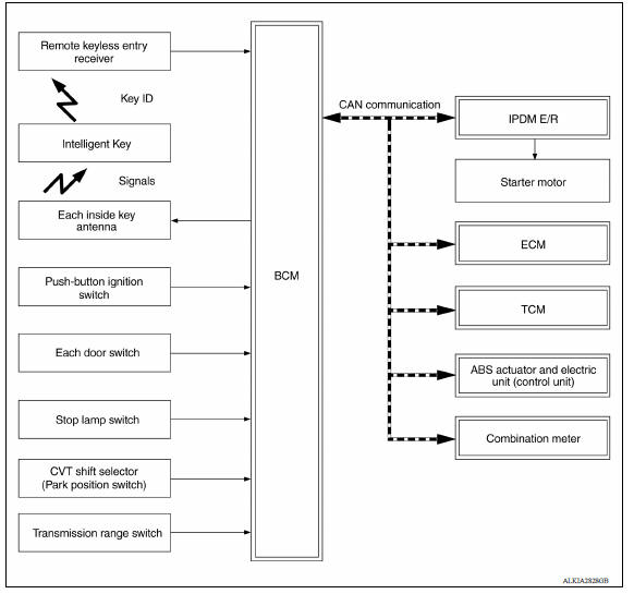
SYSTEM DESCRIPTION
- The engine start function of Intelligent Key system makes it possible to
start and stop the engine without
using the key, based on the electronic ID verification. The electronic ID
verification is performed between
BCM and Intelligent Key when the push-button ignition switch is pressed
while the Intelligent Key is within
the detection area of inside key antenna.
NOTE: The driver should carry the Intelligent Key at all times.
- Intelligent Key has 2 IDs (Intelligent Key ID and NATS ID). It can perform the door lock/unlock operation and the push-button ignition switch operation when the registered Intelligent Key is carried.
- If the ID is successfully verified, when push-button ignition switch is pressed the engine can be started.
- Up to 4 Intelligent Keys can be registered (Including the standard
Intelligent Key) upon request from the customer.
NOTE: Refer to STR "STARTING SYSTEM (WITHOUT INTELLIGENT KEY) : System Description" for any functions other than engine start function of Intelligent Key system.
PRECAUTIONS FOR INTELLIGENT KEY SYSTEM
The transponder (the chip for NATS ID verification) is integrated into the Intelligent Key. (For the conventional models, it is integrated into the mechanical key.) Therefore, ID verification cannot be performed by mechanical key only.
In that case, NATS ID verification can be performed when Intelligent Key backside is contacted to push-button ignition switch while brake pedal is depressed. If verification result is OK, engine can be started.
OPERATION WHEN INTELLIGENT KEY IS CARRIED
- When the push-button ignition switch is pressed, the BCM activates the inside key antenna and transmits the request signal to the Intelligent Key.
- The Intelligent Key receives the request signal and transmits the Intelligent Key ID signal to the BCM.
- BCM receives the Intelligent Key ID signal via remote keyless entry receiver and verifies it with the registered ID.
- BCM turns ACC relay ON and transmits the ignition power supply ON signal to IPDM E/R.
- IPDM E/R turns the ignition relay ON and starts the ignition power supply.
- IPDM E/R turns the starter control relay ON for engine starting in advance.
- BCM detects the selector lever position and brake pedal operation condition.
- BCM transmits the starter request signal to IPDM E/R and turns the starter relay in IPDM E/R ON if BCM judges that the engine start condition* is satisfied.
- Power supply is supplied through the starter relay and the starter
control relay to operate the starter motor.
CAUTION: If a malfunction is detected in the Intelligent Key system, the "KEY" warning lamp on the combination meter illuminates. At that time, the engine cannot be started.
- When BCM receives feedback signal from ECM indicating that the engine is started, the BCM transmits a stop signal to IPDM E/R and stops cranking by turning OFF the starter motor relay. (If engine start is unsuccessful, cranking stops automatically within 5 seconds.) CAUTION: When the Intelligent Key is carried outside of the vehicle (inside key antenna detection area) while the power supply is in the ACC or ON position, even if the engine start condition* is satisfied, the engine cannot be started.
*: For the engine start condition, refer to "IGNITION SWITCH POSITION CHANGE TABLE BY PUSH-BUTTON IGNITION SWITCH OPERATION".
OPERATION RANGE
Engine can be started when Intelligent Key is inside the vehicle. However, sometimes engine may not start when Intelligent Key is on instrument panel or in glove box.
ENGINE START OPERATION WHEN INTELLIGENT KEY IS CONTACTED TO PUSH-BUTTON IGNITION SWITCH
When Intelligent Key battery is discharged, NATS ID verification between transponder in Intelligent Key and BCM is performed when Intelligent Key backside is contacted to push-button ignition switch while brake pedal is depressed. If the verification result is OK, engine can be started.
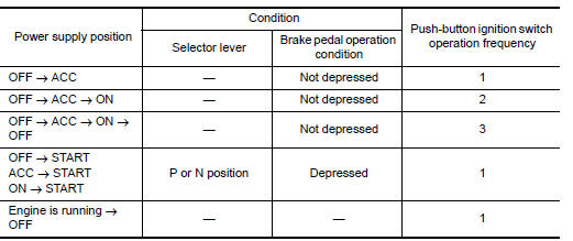
IGNITION SWITCH POSITION CHANGE TABLE BY PUSH-BUTTON IGNITION SWITCH OPERATION
The ignition switch position can be changed by the following operations.
NOTE:
- When an Intelligent Key is within the detection area of inside key antenna or when Intelligent Key backside is contacted to push-button ignition switch, it is equivalent to the operations below.
- When starting the engine, the BCM monitors under the engine start conditions,
- Brake pedal operation condition
- Selector lever position
- Vehicle speed
Vehicle speed: less than 4 km/h (2.5 MPH)
Vehicle speed: 4 km/h (2.5 MPH) or more
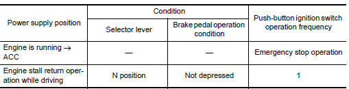
Emergency stop operation
- Press and hold the push-button ignition switch for 2 seconds or more.
- Press the push-button ignition switch 3 times or more within 1.5 seconds.
 Component parts Component parts Component parts
Component Parts Location 1. BCM (view with instrument panel removed) 2. ECM 3. IPDM E/R 4. Meter 5. Security indicator lamp 6. CVT shift selector (park position switch) (view with center c ...
Nissan anti-theft system
NISSAN ANTI-THEFT SYSTEM : System Description SYSTEM DIAGRAM SYSTEM DESCRIPTION The Nissan Anti-Theft System (NATS) prevents the engine from being started by Intelligent Key whose ID is ...
Other materials:
Key interlock cable
Exploded View
1. A/T shift selector assembly 2. Key interlock cable A: Key cylinder
B: Lock plate C: Clip
Removal and Installation
CAUTION:
Always apply the parking brake before performing removal and installation.
REMOVAL
Move the shift selector to the "N" position.
Remove the s ...
Fender protector
Exploded View
1. Fender protector 2. J-nut Front
Removal and Installation
REMOVAL
1. Remove under cover. Refer to EXT"Removal and Installation".
2. Remove fender protector screws and clips.
3. Remove fender protector.
INSTALLATION
Installation is in the reverse order of removal ...
Categories
- Manuals Home
- Nissan Versa Owners Manual
- Nissan Versa Service Manual
- Video Guides
- Questions & Answers
- External Resources
- Latest Updates
- Most Popular
- Sitemap
- Search the site
- Privacy Policy
- Contact Us

0.0052