Nissan Versa (N17): Magnet clutch
Description
SYSTEM DESCRIPTION
When the blower speed dial is in one of the fan speed positions, the front air control outputs a fan ON signal to the BCM. When the A/C switch is pressed, the A/C switch LED illuminates and the front air control outputs a compressor ON signal to the BCM. Any mode control button can be selected. As long as the BCM receives a compressor ON signal and a fan ON signal from the front air control, the conditions required for the BCM to transmit a compressor ON request to the ECM have been met.
The BCM sends a compressor ON signal to ECM, via CAN communication line.
The ECM judges whether the compressor can be turned ON, based on each sensor status (refrigerant pressure sensor signal, throttle angle sensor, etc.). If it judges the compressor can be turned ON, it sends a compressor ON signal to IPDM E/R, via CAN communication line.
Upon receipt of a compressor ON signal from ECM, IPDM E/R turns the A/C relay ON to operate the compressor.
Component Function Check
1.CHECK MAGNET CLUTCH OPERATION
Perform auto active test of IPDM E/R. Refer to PCS "CONSULT Function (IPDM E/R)" or PCS "CONSULT Function (IPDM E/R)".
Is the inspection result normal?
YES >> Inspection End.
NO >> Refer to HAC "Diagnosis Procedure".
Diagnosis Procedure
Regarding Wiring Diagram information, refer to HAC "Wiring Diagram".
1.CHECK FUSE
Check 10A fuse (No. 42, located in IPDM E/R).
NOTE: Refer to PG "IPDM E/R Terminal Arrangement".
Is the inspection result normal?
YES >> GO TO 2.
NO >> Replace the blown fuse after repairing the affected circuit.
2.CHECK MAGNET CLUTCH
- Turn ignition switch OFF.
- Disconnect compressor connector.
- Directly apply battery voltage to the magnet clutch. Check for operation visually and by sound.
Does it operate normally?
YES >> GO TO 3.
NO >> Replace magnet clutch. Refer to HA "Removal and Installation".
3.CHECK MAGNET CLUTCH POWER SUPPLY CIRCUIT FOR OPEN
- Disconnect IPDM E/R connector.
- Check continuity between IPDM E/R harness connector and compressor
harness connector.
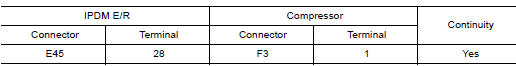
Is the inspection result normal?
YES >> Replace IPDM E/R. Refer to PCS "Removal and Installation".
NO >> Repair harness or connector.
SYMPTOM DIAGNOSIS
MANUAL AIR CONDITIONING SYSTEM
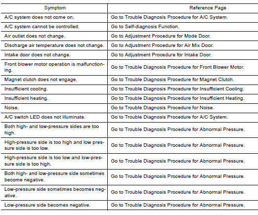
Symptom Table
 Front blower motor
Description The front blower motor utilizes a brush-less motor with a rotating magnet. Quietness is improved over previous motors where the brush was the point of contact and the coil rotated. ...
Insufficient cooling
Description Symptom Insufficient cooling No cool air comes out. (Air flow volume is normal.) Diagnosis Procedure NOTE: Perform self-diagnosis with CONSULT before performing symptom dia ...
Other materials:
Refrigerant pressure sensor
Removal and Installation for Refrigerant Pressure
Sensor
REMOVAL
CAUTION:
Do not damage the condenser fins.
Perform lubricant return operation before each refrigeration
system disassembly. However, if a large amount of refrigerant
or lubricant is detected, do not perform lubricant retur ...
BCM
Reference Value
NOTE:
The Signal Tech II Tool (J-50190) can be used to perform the following
functions. Refer to the Signal Tech II
User Guide for additional information.
Activate and display TPMS transmitter IDs
Display tire pressure reported by the TPMS transmitter
Read TPMS DTCs
...
Categories
- Manuals Home
- Nissan Versa Owners Manual
- Nissan Versa Service Manual
- Video Guides
- Questions & Answers
- External Resources
- Latest Updates
- Most Popular
- Sitemap
- Search the site
- Privacy Policy
- Contact Us

0.0064