Nissan Versa (N17): Door lock actuator
Driver side
DRIVER SIDE : Description
Locks/unlocks the door with the signal from BCM.
DRIVER SIDE : Component Function Check
1.CHECK FUNCTION
- Use CONSULT to perform Active Test ("DOOR LOCK").
- Touch "ALL LOCK" or "ALL UNLOCK" to check that it works normally.
Is the inspection result normal?
YES >> Door lock actuator is OK.
NO >> Refer to DLK "DRIVER SIDE : Diagnosis Procedure".
DRIVER SIDE : Diagnosis Procedure
Regarding Wiring Diagram information, refer to DLK "Wiring Diagram".
1.CHECK OUTPUT SIGNAL
Check voltage between BCM connector and ground. 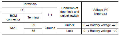
Is the inspection result normal?
YES >> GO TO 3
NO >> GO TO 2
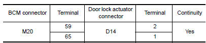
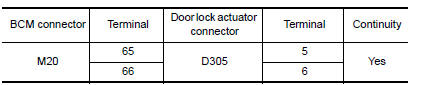
2.CHECK DOOR LOCK ACTUATOR CIRCUIT
- Turn ignition switch OFF.
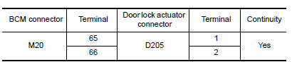
- Disconnect BCM and front door lock actuator driver side connector.
- Check continuity between BCM connector and front door lock actuator
driver side connector.
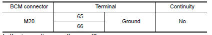
- Check continuity between BCM connector and ground.
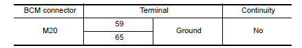
Is the inspection result normal?
YES >> Replace front door lock actuator LH.
NO >> Repair or replace harness.
3.CHECK INTERMITTENT INCIDENT
Refer to GI "Intermittent Incident".
>> Inspection End.
Passenger side
PASSENGER SIDE : Description
Locks/unlocks the door with the signal from BCM.
PASSENGER SIDE : Component Function Check
1.CHECK FUNCTION
- Use CONSULT to perform Active Test ("DOOR LOCK").
- Touch "ALL LOCK" or "ALL UNLOCK" to check that it works normally.
Is the inspection result normal?
YES >> Door lock actuator is OK.
NO >> Refer to DLK "PASSENGER SIDE : Diagnosis Procedure".
PASSENGER SIDE : Diagnosis Procedure
Regarding Wiring Diagram information, refer to DLK "Wiring Diagram".
1.CHECK DOOR LOCK ACTUATOR SIGNAL
Check voltage between BCM connector and ground. 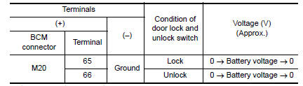
Is the inspection result normal?
YES >> GO TO 3
NO >> GO TO 2
2.CHECK DOOR LOCK ACTUATOR CIRCUIT
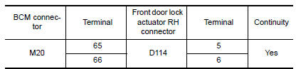
- Disconnect BCM and front door lock actuator RH connectors.
- Check continuity between BCM connector and front door lock actuator RH.
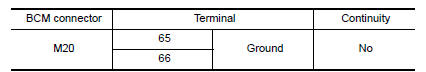
- Check continuity between BCM connector and ground.
Is the inspection result normal?
YES >> Replace front door lock actuator RH.
NO >> Repair or replace harness.
3.CHECK INTERMITTENT INCIDENT
Refer to GI "Intermittent Incident".
>> Inspection End.
Rear LH
REAR LH : Description
Locks/unlocks the door with the signal from BCM.
REAR LH : Component Function Check
1.CHECK FUNCTION
- Use CONSULT to perform Active Test ("DOOR LOCK").
- Touch "ALL LOCK" or "ALL UNLOCK" to check that it works normally.
Is the inspection result normal?
YES >> Door lock actuator is OK.
NO >> Refer to DLK "REAR LH : Diagnosis Procedure".
REAR LH : Diagnosis Procedure
Regarding Wiring Diagram information, refer to DLK "Wiring Diagram".
1.CHECK DOOR LOCK ACTUATOR SIGNAL
Check voltage between BCM connector and ground. 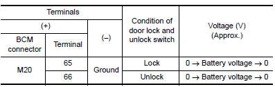
Is the inspection result normal?
YES >> GO TO 3
NO >> GO TO 2
2.CHECK DOOR LOCK ACTUATOR CIRCUIT
- Disconnect BCM and rear door lock actuator LH connectors.
- Check continuity between BCM connector and rear door lock actuator LH
connectors.
- Check continuity between BCM connector and ground.


Is the inspection result normal?
YES >> Replace rear door lock actuator LH.
NO >> Repair or replace harness.
3.CHECK INTERMITTENT INCIDENT
Refer to GI "Intermittent Incident".
>> Inspection End.
Rear RH
REAR RH : Description
Locks/unlocks the door with the signal from BCM.
REAR RH : Component Function Check
1.CHECK FUNCTION
- Use CONSULT to perform Active Test ("DOOR LOCK").
- Touch "ALL LOCK" or "ALL UNLOCK" to check that it works normally.
Is the inspection result normal?
YES >> Door lock actuator is OK.
NO >> Refer to DLK "REAR RH : Diagnosis Procedure".
REAR RH : Diagnosis Procedure
Regarding Wiring Diagram information, refer to DLK "Wiring Diagram".
1.CHECK DOOR LOCK ACTUATOR SIGNAL
Check voltage between BCM connector and ground. 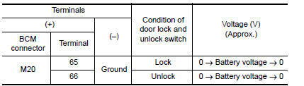
Is the inspection result normal?
YES >> GO TO 3
NO >> GO TO 2
2.CHECK DOOR LOCK ACTUATOR CIRCUIT
- Disconnect BCM and rear door lock actuator RH connectors.
- Check continuity between BCM connector and rear door lock actuator RH
connectors.
- Check continuity between BCM connector and ground.
Is the inspection result normal?
YES >> Replace rear door lock actuator RH.
NO >> Repair or replace harness.
3.CHECK INTERMITTENT INCIDENT
Refer to GI "Intermittent Incident".
>> Inspection End.
 Key switch (BCM Input)
Diagnosis Procedure Regarding Wiring Diagram information, refer to DLK "Wiring Diagram". 1.CHECK KEY SWITCH INPUT SIGNAL With CONSULT Check k ...
Trunk lid opener actuator
Component Function Check 1.CHECK FUNCTION Press the trunk release button on the keyfob and check that the trunk lid opens. Is the inspection result normal? YES >> Inspection End. NO > ...
Other materials:
Precaution
Precaution for Supplemental Restraint System
(SRS) "AIR BAG" and "SEAT BELT PRETENSIONER"
The Supplemental Restraint System such as "AIR BAG" and "SEAT BELT
PRETENSIONER", used along
with a front seat belt, helps to reduce the risk or severity of injury to the
driver and f ...
Air conditioning cut control
AIR CONDITIONING CUT CONTROL : System Diagram
AIR CONDITIONING CUT CONTROL : System
Description
INPUT/OUTPUT SIGNAL CHART
Sensor
Input signal to ECM
ECM function
Actuator
Crankshaft position sensor (POS)
Camshaft position sensor (PHASE)
Engine speed*1
Pisto ...
Categories
- Manuals Home
- Nissan Versa Owners Manual
- Nissan Versa Service Manual
- Video Guides
- Questions & Answers
- External Resources
- Latest Updates
- Most Popular
- Sitemap
- Search the site
- Privacy Policy
- Contact Us

0.0068