Nissan Versa (N17): Steering column
Exploded View
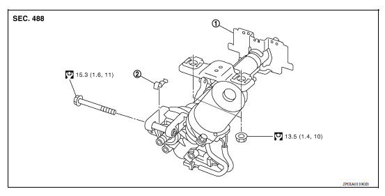
1. Steering column assembly 2. Clamp
Removal and Installation
REMOVAL
CAUTION:
- Keep steering column assembly away from magnetic sources.
- Do not disassemble steering column assembly.
- While removing the steering column assembly, do not move the steering gear.
- When removing the steering column assembly, be careful not to allow the intermediate shaft to turn.
- Set vehicle to the straight-ahead position.
- Place the steering column tilt to the lowest selection.
- Remove instrument lower panel LH. Refer to IP, "Removal and Installation".
- Remove driver air bag module. Refer to SR"Removal and Installation".
- Remove steering wheel. Refer to ST "Exploded View".
- Remove steering column covers. Refer to IP "Removal and Installation".
- Remove spiral cable. Refer to SR "Removal and Installation".
- Remove combination switch. Refer to EXL "Exploded View"
- Remove the cluster lid A. Refer to IP "Removal and Installation"
- Disconnect the harness connectors from the steering switch.
- Remove the key cylinder only if the steering column is being replaced. Refer to TM "Removal and Installation".
- Place the steering column tilt to the middle selection.
CAUTION: Do not change the position of the tilt mechanism until the steerign column is reinstalled.
- Loosen the steering shaft lower joint bolt.
- Remove the intermediate shaft upper bolt and separate intermediate shaft
from steering column assembly.
Refer to ST "Removal and Installation".
CAUTION:
- Place a matching mark on both intermediate shaft and steering column assembly before removing intermediate shaft.
- When removing intermediate shaft, do not insert any tool into the yoke groove to pull out the intermediate shaft or damage could occur. Replace intermediate shaft with a new one if damaged.
- Disconnect the harness connectors from EPS control unit.
- Remove steering column assembly.
- Remove EPS control unit from steering column assembly. Refer to STC "Removal and Installation".
- Remove clamp from steering column assembly.
- Perform inspection after removal. Refer to ST "Inspection".
INSTALLATION
CAUTION:
- Do not impact on the axis when removing steering column assembly.
- When installing the steering column cover, check that the vehicle harness is not stuck in the cover.
Installation is in the reverse order of removal.
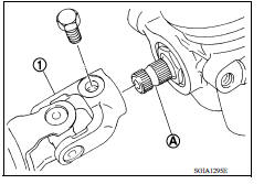
- For intermediate shaft bolt direction, refer to ST "Exploded View".
- When connecting intermediate shaft upper side (1) and column shaft, make sure the bolt is securely seated in groove (A) of column shaft before final tightening.
- After installing steering column assembly, perform self-diagnosis with CONSULT to ensure correct operation. Refer to STC "CONSULT Function".
- Perform inspection after installation. Refer to ST "Inspection".
Inspection
INSPECTION AFTER REMOVAL
- Check each part of steering column assembly for damage or other malfunctions. Replace if there are any abnormal conditions.
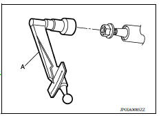
- Measure steering column rotating torque using Tool (A). Replace steering column assembly if the rotating torque is outside the standard.
Tool number : - (J-25765-A)
Rotating torque : Refer to ST "Steering Column Operating Range".
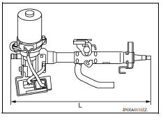
- Measure the steering column length (L) as shown, if vehicle has been involved in a minor collision. Replace steering column assembly (with motor, reduction gear, sensor) if (L) is outside the standard.
Steering column length (L) : Refer to ST "Steering Column Operating Range".
INSPECTION AFTER INSTALLATION
- Check each part of steering column assembly for damage or other malfunctions. Replace if there are any abnormal conditions.
- Check the steering wheel play, neutral position steering wheel, steering wheel turning force, and front wheel turning angle. Refer to ST "Inspection".
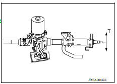
- Check tilt mechanism operating range (T) as shown.
Tilt operating range (T) : Refer to ST "Steering Column Operating Range".
 Steering wheel
Exploded View 1. Steering wheel Removal and Installation REMOVAL NOTE: When reconnecting spiral cable, secure cable with a tape so that case and rotating part stay aligned. This will omi ...
Steering shaft
Exploded View 1. Lower joint 2. Intermediate shaft 3. Steering column assembly ...
Other materials:
Before starting the engine
Make sure the area around the vehicle is
clear.
Check fluid levels such as engine oil, coolant,
brake and clutch fluid (if so equipped),
and windshield-washer fluid as frequently as
possible, or at least whenever you refuel.
Check that all windows and lights are clean.
Visually insp ...
Jump starting
To start your engine with a booster battery, the
instructions and precautions below must be followed.
WARNING
If done incorrectly, jump starting can
lead to a battery explosion, resulting in
severe injury or death. It could also
damage your vehicle.
Explosive hydrogen gas is always pre ...
Categories
- Manuals Home
- Nissan Versa Owners Manual
- Nissan Versa Service Manual
- Video Guides
- Questions & Answers
- External Resources
- Latest Updates
- Most Popular
- Sitemap
- Search the site
- Privacy Policy
- Contact Us

0.0066