Nissan Versa (N17): Trouble diagnosis
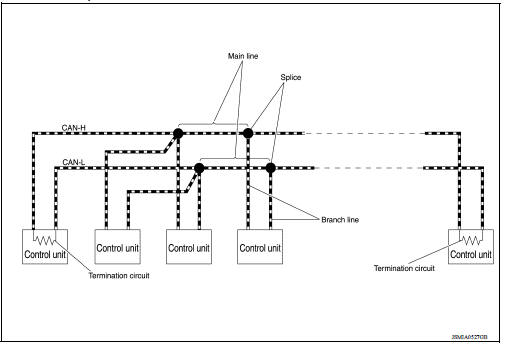
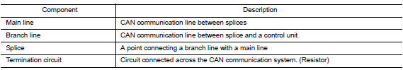
Component Description
Condition of Error Detection
DTC (e.g. U1000 and U1001) of CAN communication is indicated on SELF-DIAG RESULTS on CONSULT if a CAN communication signal is not transmitted or received between units for 2 seconds or more.
CAN COMMUNICATION SYSTEM ERROR
- CAN communication line open (CAN-H, CAN-L, or both)
- CAN communication line short (ground, between CAN communication lines, other harnesses)
- Error of CAN communication control circuit of the unit connected to CAN communication line
WHEN DTC OF CAN COMMUNICATION IS INDICATED EVEN THOUGH CAN COMMUNICATION SYSTEM IS NORMAL
- Removal/installation of parts: Error may be detected when removing and installing CAN communication unit and related parts while turning the ignition switch ON. (A DTC except for CAN communication may be detected.)
- Fuse blown out (removed): CAN communication of the unit may cease.
- Voltage drop: Error may be detected if voltage drops due to discharged battery when turning the ignition switch ON (Depending on the control unit which carries out CAN communication).
- Error may be detected if the power supply circuit of the control unit, which carries out CAN communication, malfunctions (Depending on the control unit which carries out CAN communication).
- Error may be detected if reprogramming is not completed normally.
NOTE: CAN communication system is normal if DTC of CAN communication is indicated on SELF-DIAG RESULTS of CONSULT under the above conditions. Erase the memory of the self-diagnosis of each control unit.
Symptom When Error Occurs in CAN Communication System
In CAN communication system, multiple control units mutually transmit and receive signals. Each control unit cannot transmit and receive signals if any error occurs on CAN communication line. Under this condition, multiple control units related to the root cause malfunction or go into fail-safe mode.
ERROR EXAMPLE
NOTE: Each vehicle differs in symptom of each control unit under fail-safe mode and CAN communication line wiring.
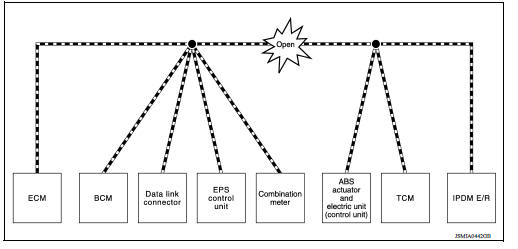
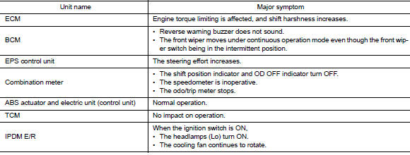
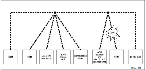
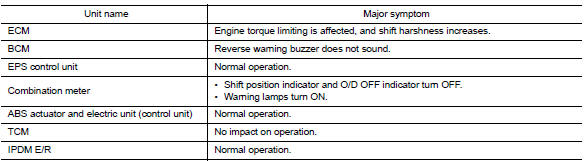
Example: Main Line Between Data Link Connector and ABS Actuator and Electric Unit (Control Unit) Open Circuit
Example: TCM Branch Line Open Circuit
NOTE: The model (all control units on CAN communication system are Diag on CAN) cannot perform CAN diagnosis with CONSULT if the following error occurs. The error is judged by the symptom.
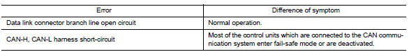
Example: Data Link Connector Branch Line Open Circuit
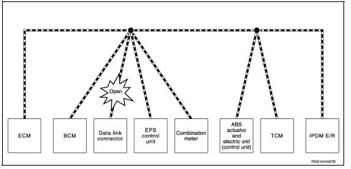
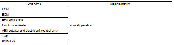
NOTE: When data link connector branch line is open, transmission and reception of CAN communication signals are not affected. Therefore, no symptoms occur. However, be sure to repair malfunctioning circuit.
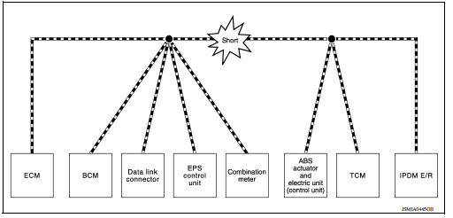
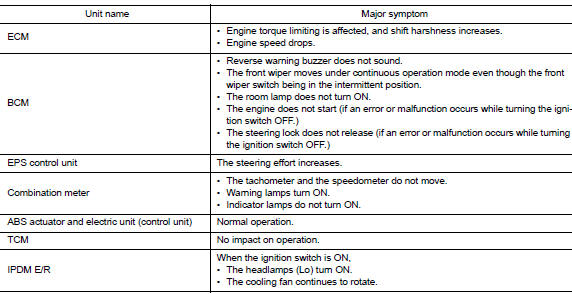
Example: CAN-H, CAN-L Harness Short Circuit
CAN Diagnosis with CONSULT
CAN diagnosis on CONSULT extracts the root cause by receiving the following information.
- Response to the system call
- Control unit diagnosis information
- Self-diagnosis
- CAN diagnostic support monitor
Self-Diagnosis
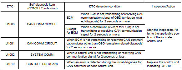
If communication signals cannot be transmitted or received among control units communicating via CAN communication line, CAN communication-related DTC is displayed on the CONSULT "Self Diagnostic Result" screen.
NOTE: The following table shows examples of CAN communication-related DTC. For other DTC, refer to the applicable sections.
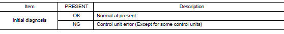
CAN Diagnostic Support Monitor
MONITOR ITEM (CONSULT)
Example: CAN DIAG SUPPORT MNTR indication
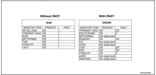
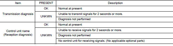
Without PAST
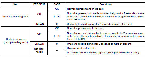
With PAST
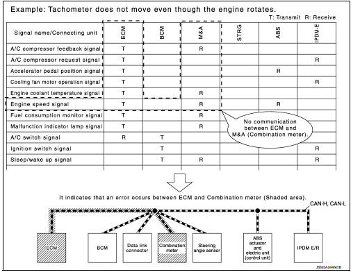
How to Use CAN Communication Signal Chart
The CAN communication signal chart lists the signals transmitted/received among control units. It is useful for detecting the root cause by finding a signal related to the symptom, and by checking transmission and reception unit.
BASIC INSPECTION
 System
CAN COMMUNICATION SYSTEM CAN COMMUNICATION SYSTEM : System Description CAN (Controller Area Network) is a serial communication line for real time application. It is an on-vehicle multiplex commun ...
Diagnosis and repair workflow
Trouble Diagnosis Flow Chart Trouble Diagnosis Procedure INTERVIEW WITH CUSTOMER Interview with the customer is important to detect the root cause of CAN communication system errors and t ...
Other materials:
Preparation
Special Service Tools
The actual shapes of KentMoore tools may differ from those of special
service tools illustrated here.
Tool number
(KentMoore No.)
Tool name
Description
ST25051001
(J256951)
Oil pressure gauge &nbs ...
Oil filter
Removal and Installation
REMOVAL
Remove engine under cover.
Drain engine oil.
Remove oil filter using Tool (A).
: Front
Tool number : KV10115801 (J38956)
WARNING:
Be careful not to get burned; engine and engine oil may be
hot.
CAUTION:
When removing, prepare a shop cl ...
Categories
- Manuals Home
- Nissan Versa Owners Manual
- Nissan Versa Service Manual
- Video Guides
- Questions & Answers
- External Resources
- Latest Updates
- Most Popular
- Sitemap
- Search the site
- Privacy Policy
- Contact Us

0.0064