
Nissan Versa (N17): Rear shock absorber
Exploded View
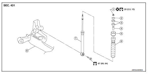
1. Piston rod lock nut 2. Washer 3. Bushing 4. Distance tube 5. Bound bumper cover 6. Bound bumper 7. Shock absorber assembly 8. Rear suspension beam
Removal and Installation
REMOVAL
- Remove the wheel and tire assembly using power tool. Refer to WT "Adjustment".
- Remove wheel sensor and sensor harness. Refer to BRC "REAR WHEEL SENSOR : Removal and Installation".
- Position a suitable jack under rear suspension beam. CAUTION: Place the jack in the center of the suspension beam. Do not damage the suspension beam with jack.
- Remove the lower shock absorber bolt.
- Remove trunk side finisher. Refer to INT "TRUNK SIDE FINISHER : Removal and Installation".
- Remove the upper shock absorber nut, washer and bushing.
- Remove shock absorber assembly.
- Remove bushing, distance tube, bound bumper cover, and bound bumper from shock absorber assembly.
INSTALLATION
Installation is in the reverse order of removal.
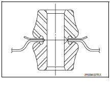
- Perform final tightening of bolts and nuts at the shock absorber lower side (rubber bushing), under unladen conditions with tires on level ground.
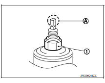
- Hold the head (A) of shock absorber piston rod (1) to keep it from rotating, and tighten piston rod lock nut.
- Perform inspection after installation. Refer to RSU "Inspection".
- After replacing the shock absorber, always follow the disposal procedure to discard the shock absorber. Refer to RSU "Disposal".
Inspection
INSPECTION AFTER REMOVAL
Shock Absorber
Check the following items, and replace the part if necessary.
- Shock absorber for deformation, cracks, and other damage.
- Piston rod for damage, uneven wear, and distortion.
- Oil leakage
Bound Bumper, Bushing
Check for cracks and damage. Replace it if necessary.
Washer, Bound Bumper Cover, Distance Tube
- Check for cracks and damage. Replace it if necessary.
INSPECTION AFTER INSTALLATION
Check wheel alignment. Refer to RSU "Inspection".
Disposal
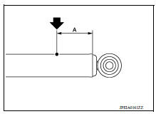
- Set shock absorber horizontally to the ground with the piston rod fully extracted.
- Drill 2 - 3 mm (0.08 - 0.12 in) hole at the position (
 ) from top
as shown to release gas gradually.
) from top
as shown to release gas gradually.
CAUTION:
- Wear eye protection (safety glass).
- Wear gloves.
- Be careful with metal chips or oil blown out by the compressed gas.
NOTE:
- Drill vertically in this direction.
- Directly to the outer tube avoiding brackets.
- The gas is clear, colorless, odorless, and harmless.
(A) : 20 - 30 mm (0.79 - 1.18 in)
3. Position the drilled hole downward and drain oil by moving the piston rod several times.
CAUTION: Dispose of drained oil according to the law and local regulations.
 Wheel alignment
Inspection DESCRIPTION CAUTION: The adjustment mechanisms of camber and toe-in are not included. If camber and toe-in is outside the standard, check front suspension parts for wear and dama ...
Coil spring
Exploded View 1. Upper rubber seat 2. Coil spring 3. Lower rubber seat 4. Rear suspension beam Removal and Installation REMOVAL Remove the wheel and tire assemblies using power tool. Refe ...
Other materials:
Before starting the engine
Make sure the area around the vehicle is
clear.
Check fluid levels such as engine oil, coolant,
brake and clutch fluid (if so equipped),
and windshield-washer fluid as frequently as
possible, or at least whenever you refuel.
Check that all windows and lights are clean.
Visually insp ...
Door mirror remote control
switch
Removal and Installation
REMOVAL
1. Remove the instrument lower panel LH (1). Refer to IP
"Removal and Installation".
2. Remove door mirror remote control switch (1) from the
instrument
lower panel LH using a suitable tool.
: Pawl
INSTALLATION
Installation is in the reverse o ...
Categories
- Manuals Home
- Nissan Versa Owners Manual
- Nissan Versa Service Manual
- Video Guides
- Questions & Answers
- External Resources
- Latest Updates
- Most Popular
- Sitemap
- Search the site
- Privacy Policy
- Contact Us

0.0107