Nissan Versa (N17): Door mirror assembly
DOOR MIRROR ASSEMBLY : Removal and Installation
REMOVAL
CAUTION: Use the following steps to disengage the door mirror corner cover from the mirror assembly. Other methods to remove the door mirror corner cover may damage the pawls.
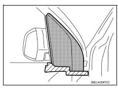
1. Remove door mirror corner cover.
a. Fully open door window.
b. Apply protective tape where the door mirror corner cover contacts the front door finisher.
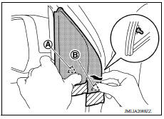
c. Hold pawl (A) so it may not be pulled outward, then pull the front end of the mirror corner cover outward to disengage pawl (B).
 Pawl
Pawl
CAUTION: Hold pawl (A) so that it will not be pulled outward or pawl (A) will be damaged.
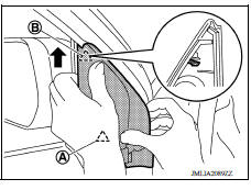
d. Slide door mirror corner cover slightly upward and disengage pawl (B), while holding pawl (A) so that it may not be pulled outward.
 Pawl
Pawl
CAUTION: Hold pawl (A) so that it will not be pulled outward or pawl (A) will be damaged.
e. While holding pawl (A) and slightly opening lower portion of door mirror corner cover, disengage pawl (A) from front door panel.
 Pawl
Pawl
CAUTION:
- Do not pull pawl (A) outward. Pawl (A) will be damaged if it is pulled outward.
- Be careful to remove, visually checking the engagement status of pawl (A) from clearance between door panel and door mirror corner cover, as indicated by the arrow (D).
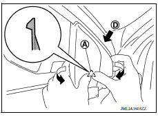
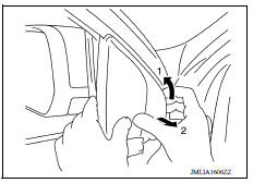
f. While slightly lifting lower portion of door mirror corner cover, slowly tilt door mirror corner cover upward as indicated by the arrow (1). Pull front end forward as indicated by the arrow (2) and remove door mirror corner cover.
CAUTION: During removal, visually check the engagement status of pawl from clearance between door panel and door mirror corner cover.
2. Remove front door finisher. Refer to INT "Removal and Installation".
3. Disconnect the harness connector from the door mirror.
4. Remove door mirror nuts and the door mirror assembly.
INSTALLATION
Installation is in the reverse order or removal.
CAUTION:
- When installing, check visually door mirror corner cover pawls. Install a new door mirror corner cover if they have been damaged.
- When installing door mirror corner cover, check that pawls are securely fitted in door panel, then press pawls in.
 Inside mirror
Removal and Installation REMOVAL 1. Hold the inside mirror at the base and push upward to release the retainer, then remove the mirror using a suitable tool under the base of the inside mirror. C ...
Front door corner finisher
FRONT DOOR CORNER FINISHER : Removal and Installation REMOVAL 1. Apply protective tape (A) on the door panel. Disengage the pawls and remove front door corner finisher using a suitable tool (B) ...
Other materials:
Brake and clutch (if so equipped) fluid
For additional information on brake fluid specification,
refer to "Recommended fluids/lubricants
and capacities" in the "Technical and consumer
information" section of this manual.
WARNING
Use only new fluid from a sealed container.
Old, inferior or contaminated
fluid may damage the br ...
Accelerator control system
Exploded View
1. Accelerator pedal assembly 2. Brake pedal bracket A. Locating hook
B. Locating pin
Removal and Installation
CAUTION:
Do not disassemble accelerator pedal assembly. Do not remove
accelerator pedal position sensor
from accelerator pedal assembly.
Avoid impact from ...
Categories
- Manuals Home
- Nissan Versa Owners Manual
- Nissan Versa Service Manual
- Video Guides
- Questions & Answers
- External Resources
- Latest Updates
- Most Popular
- Sitemap
- Search the site
- Privacy Policy
- Contact Us

0.0056